I. Intro
Date: April 2024 – June 2024
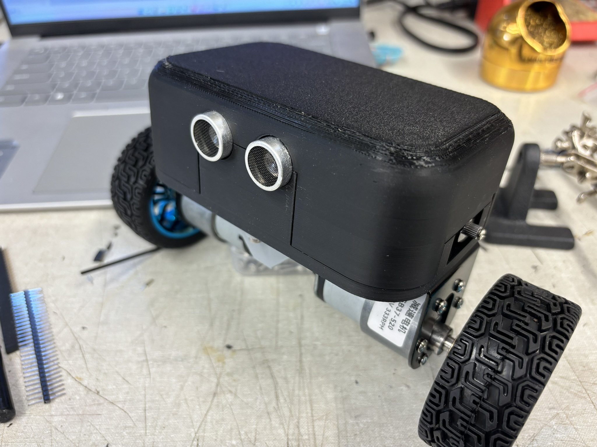
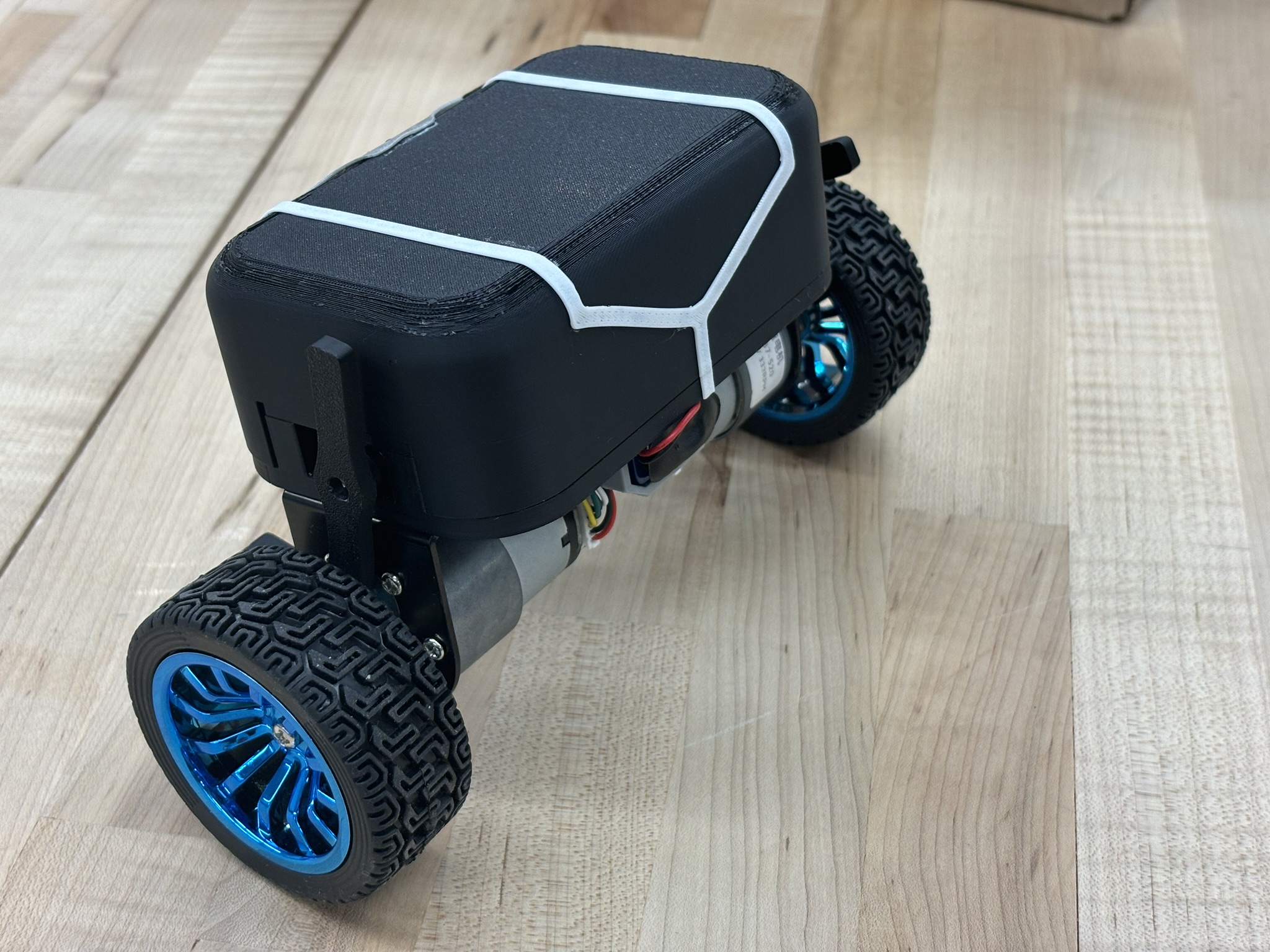
Since there’s not much progress in tuning the PID of the quadcopter, I decided to leave it for the summer and start the self balance bot project. Many people did this, so I think this project is one of the “I must do it” projects.
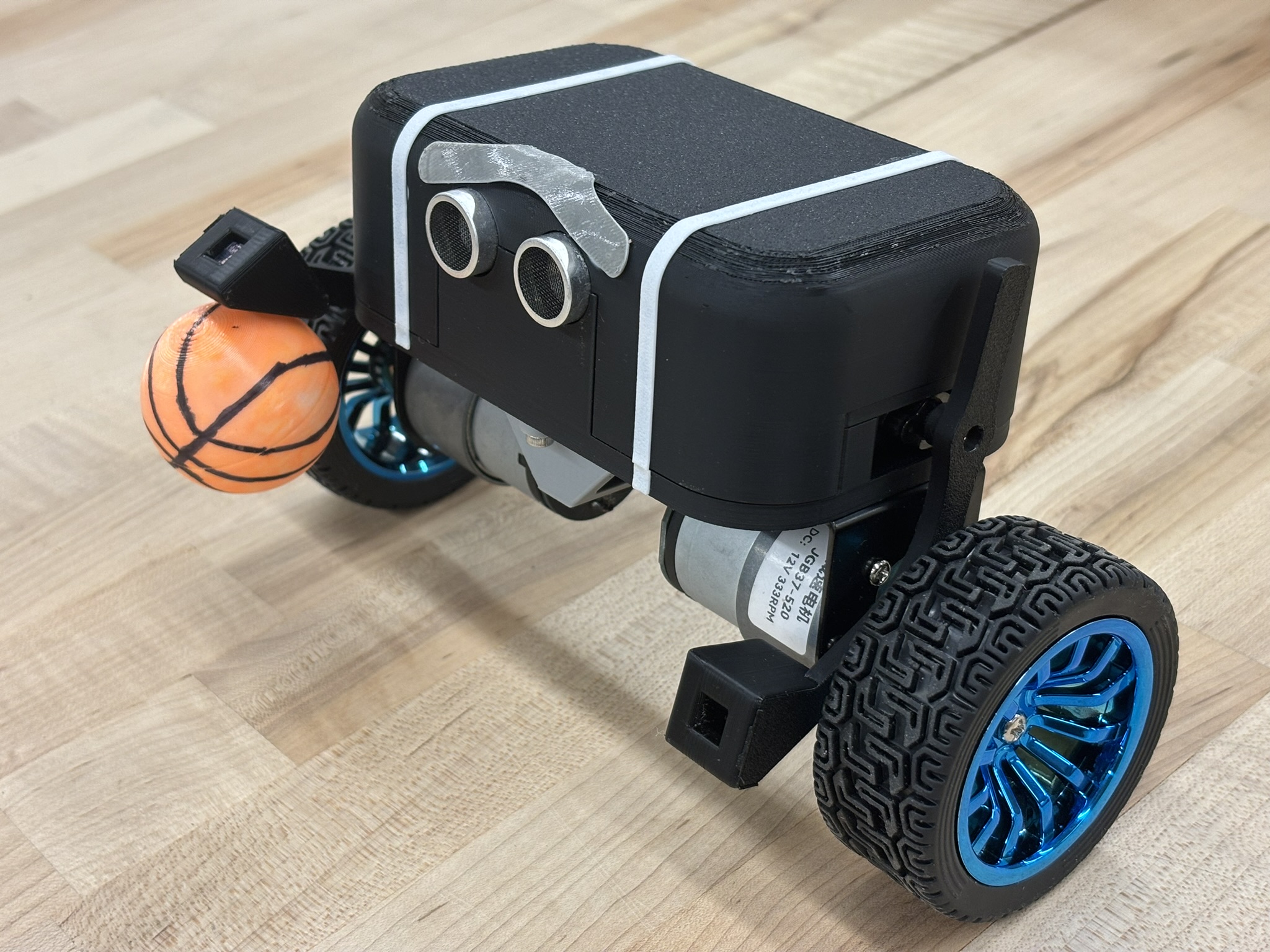
The reason that the first self balance bot failed was because the friction was too large, or the start-up voltage was very high. The PWM signal ranges from 0 to 4096, and the motor from myRIO robot requires 2500 to start spinning. That’s about 61%. In contrast, the new motor only requires 500 to spin. However, I didn’t use the friction compensation because the balancing result was much better without it. Strange.
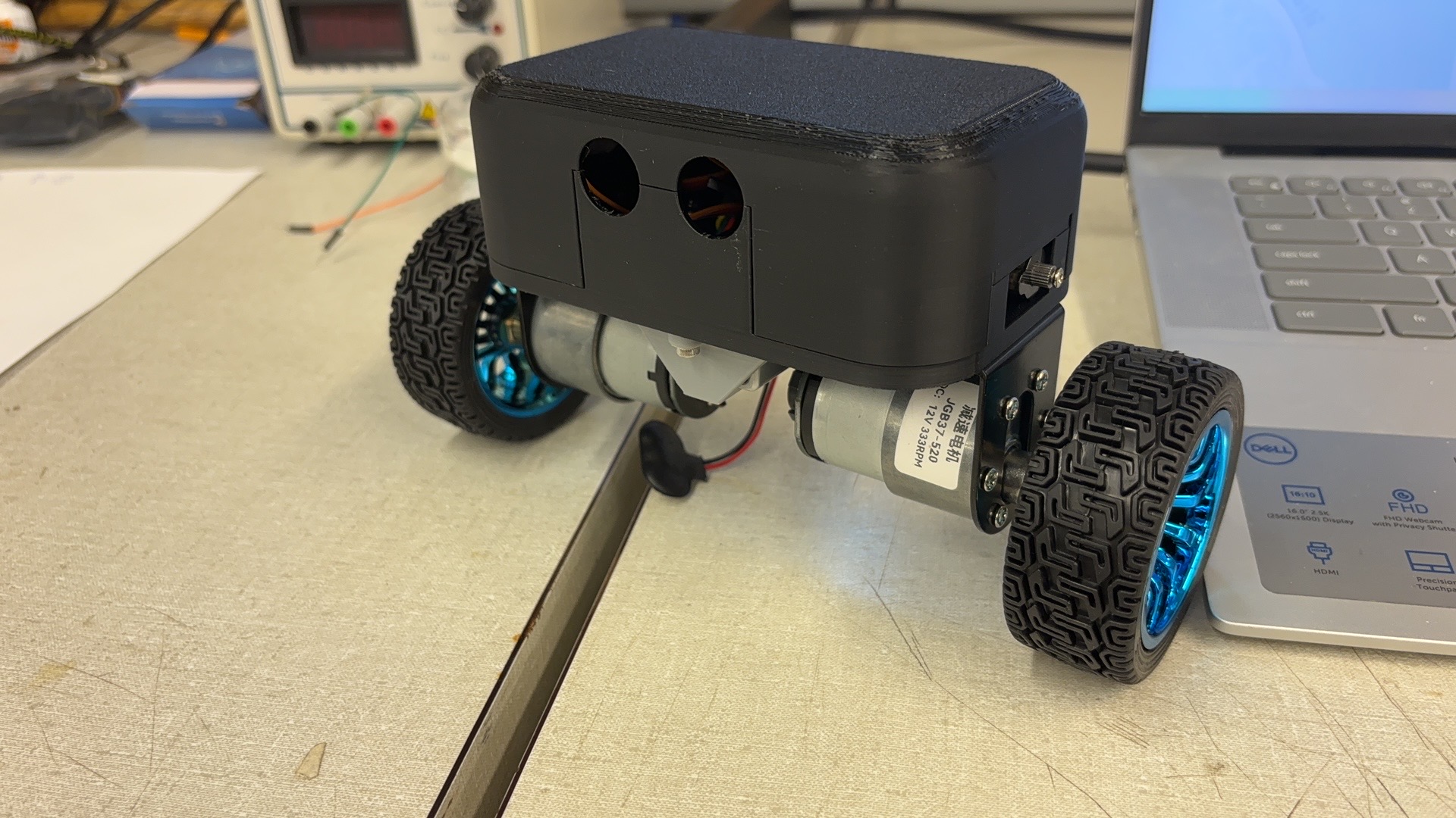
Honestly, this self balance bot has the best looking on YouTube in my opinion.
II. Building Process
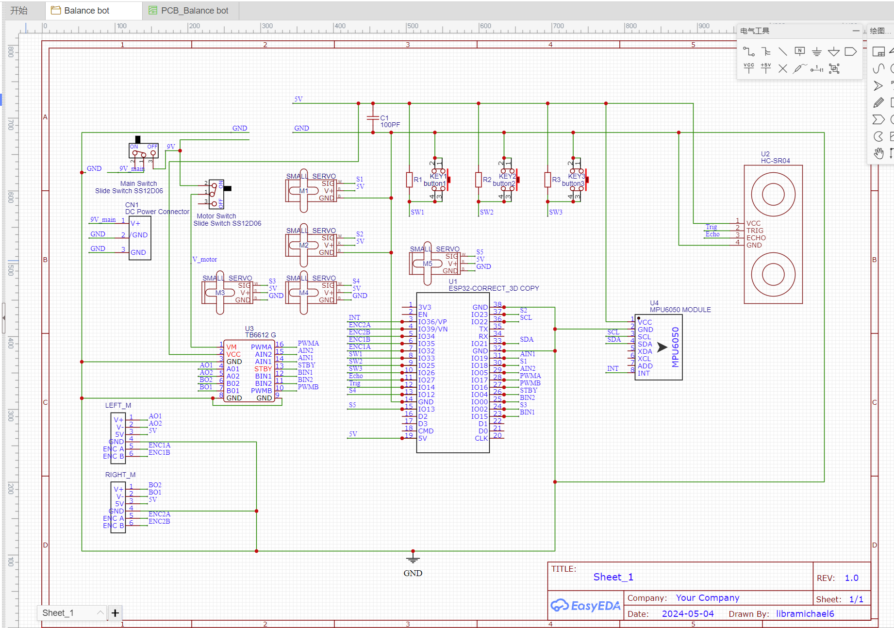
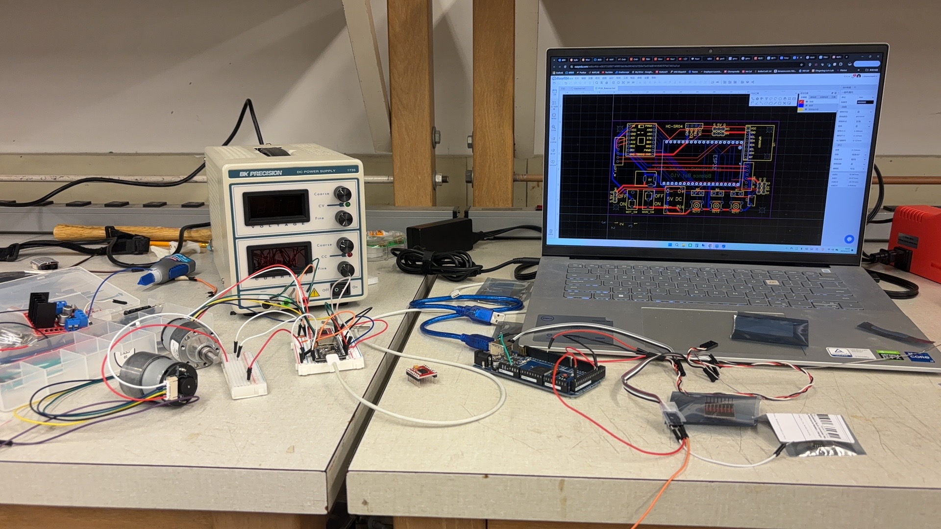
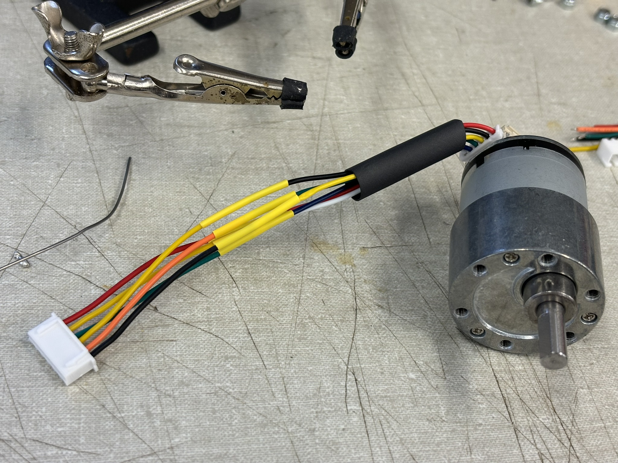
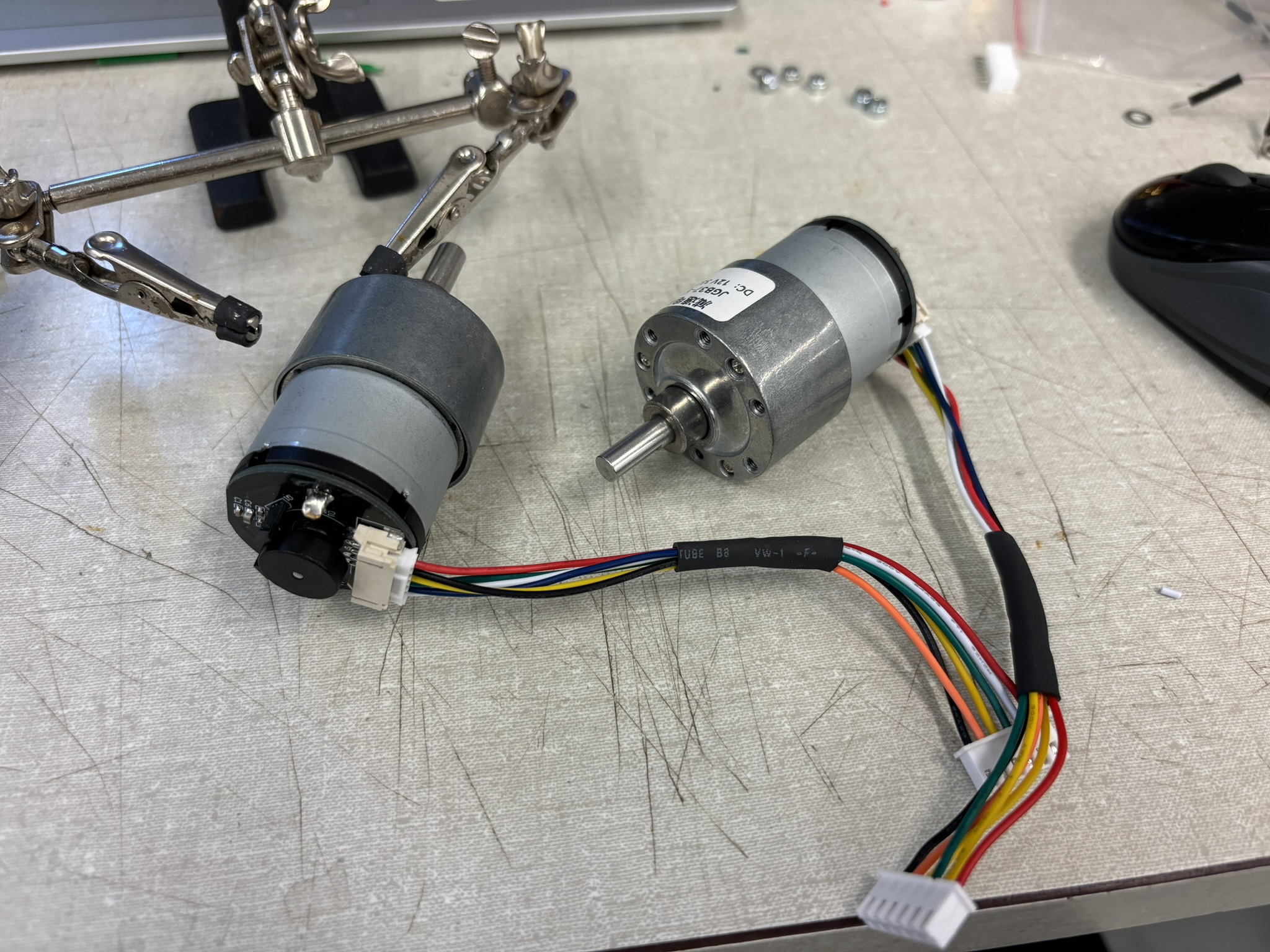
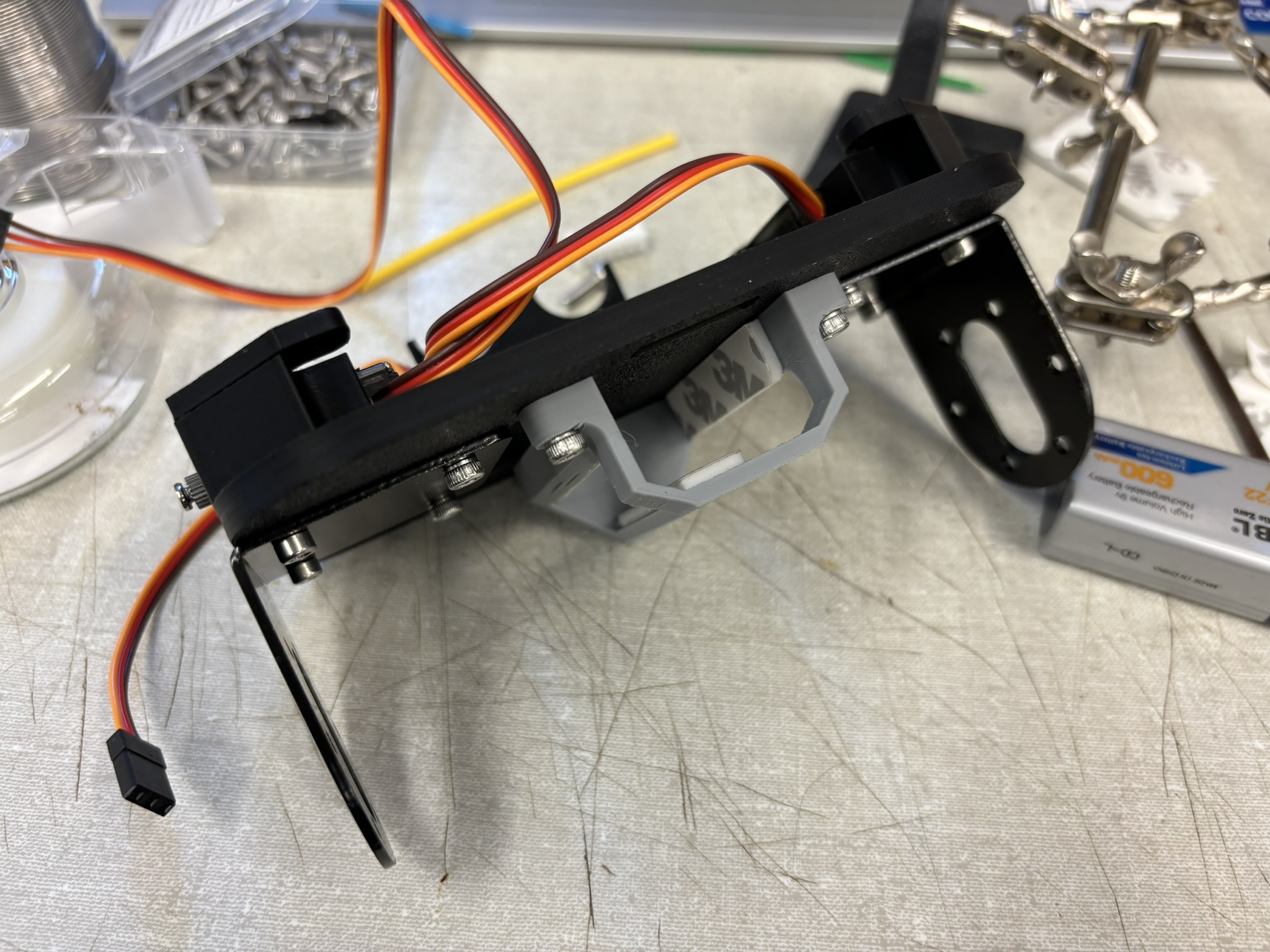
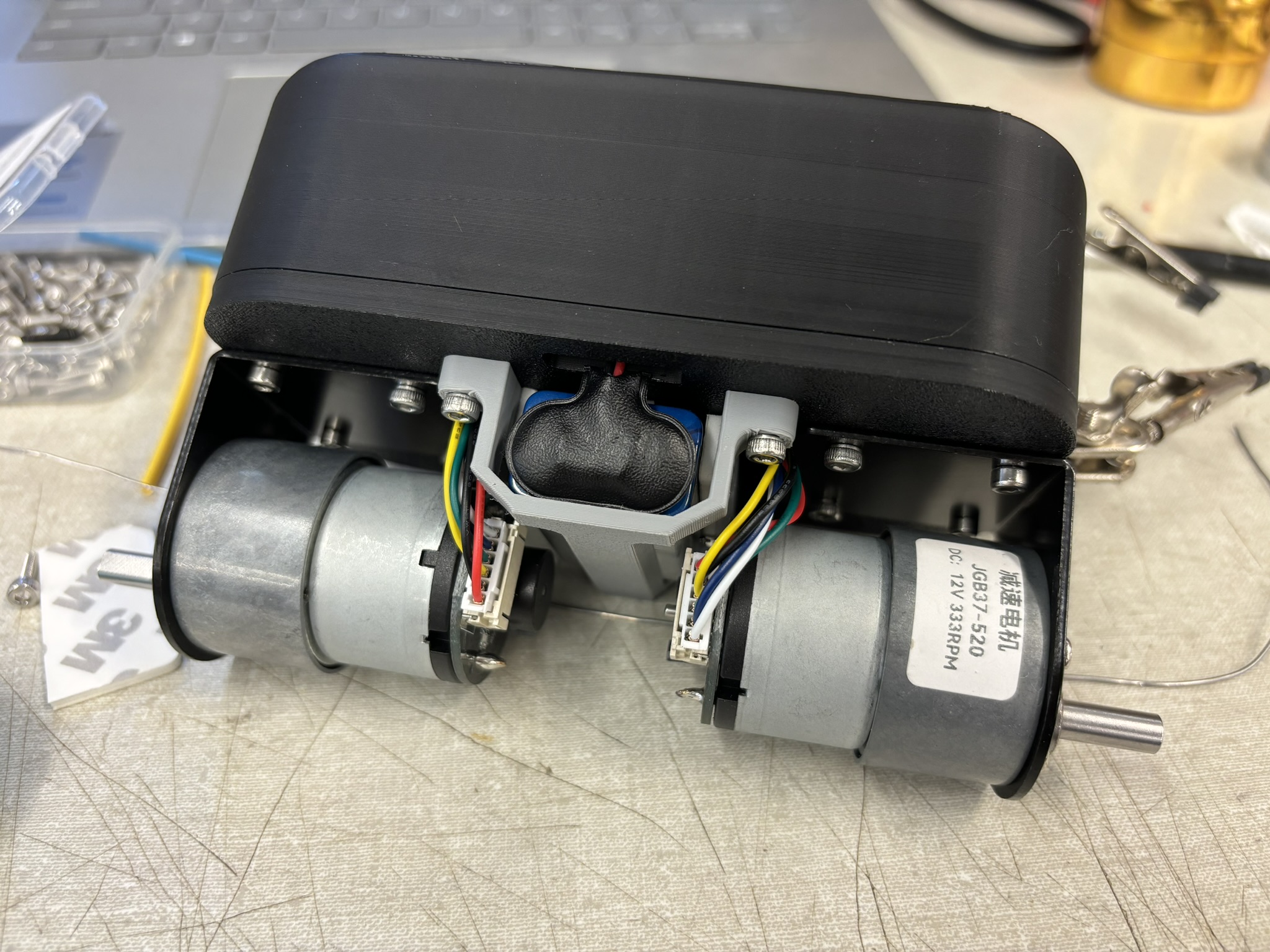
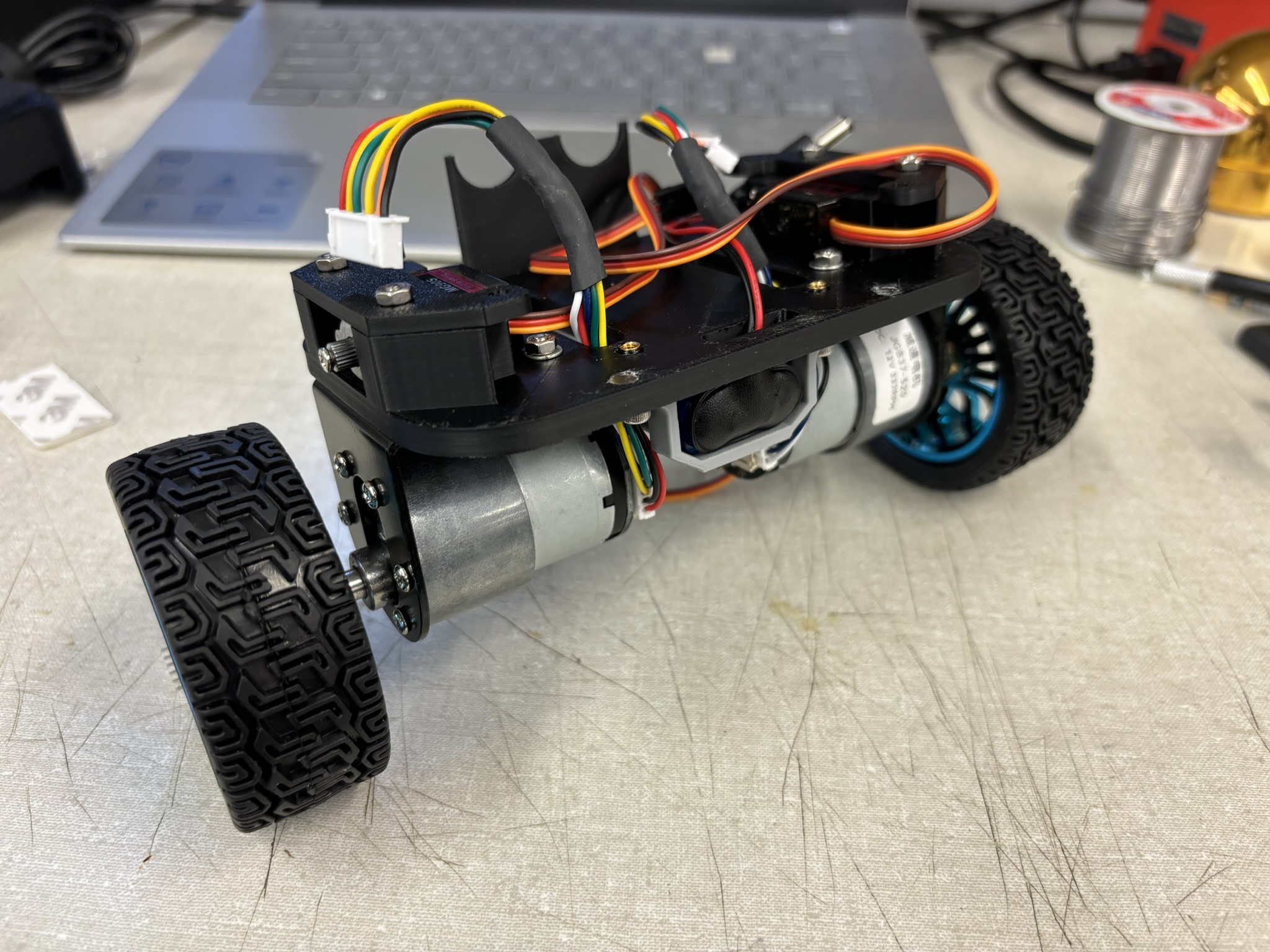
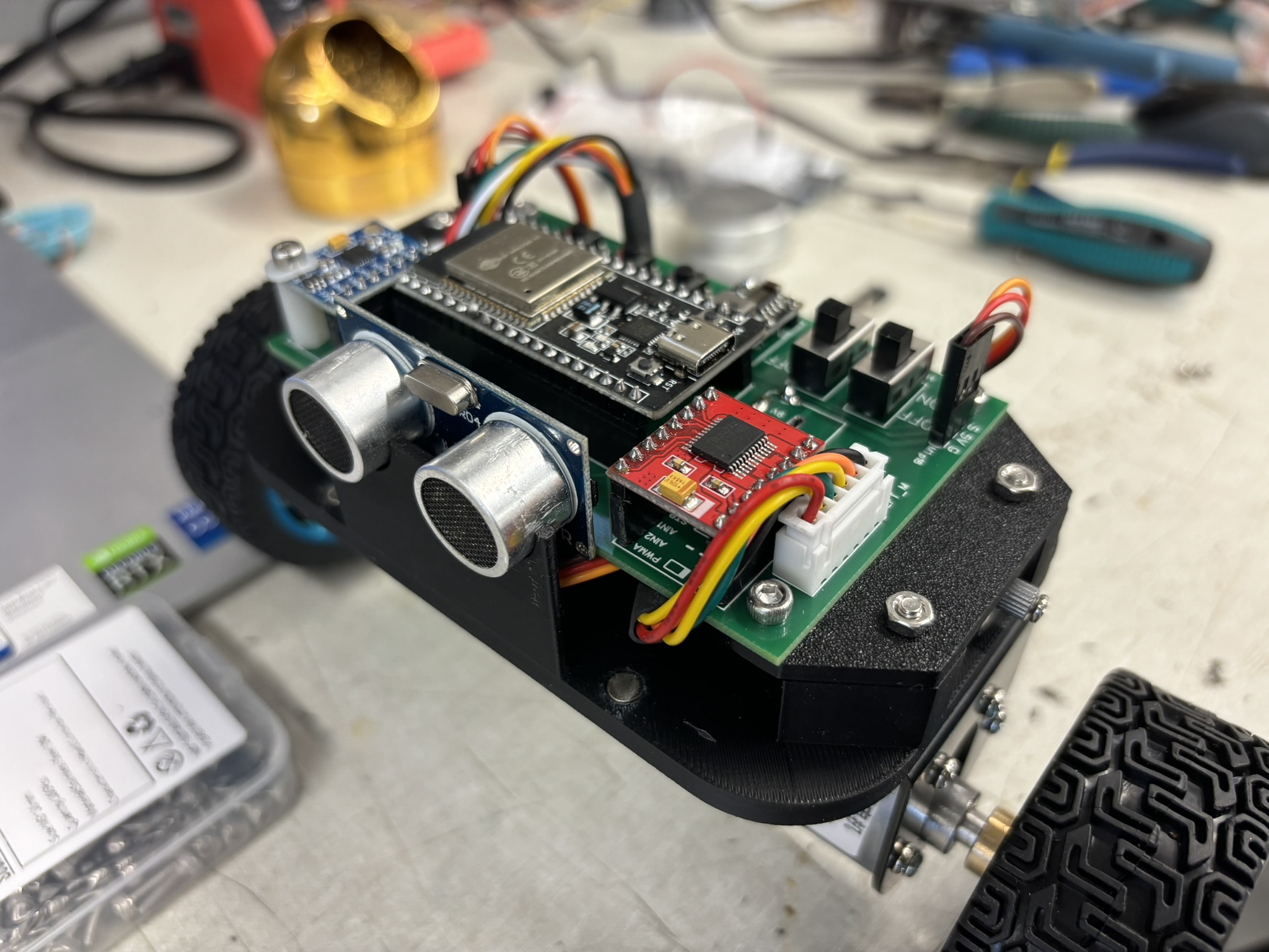
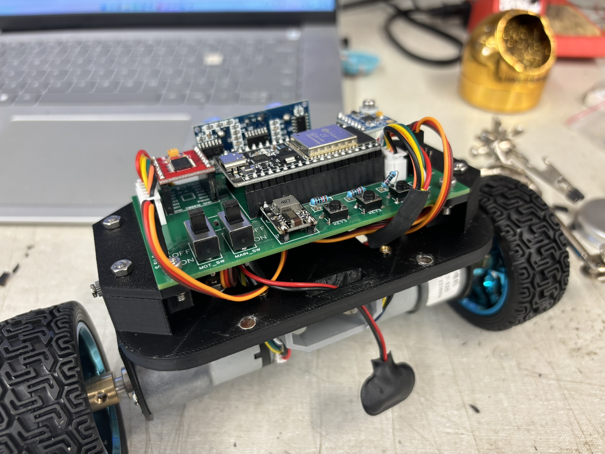
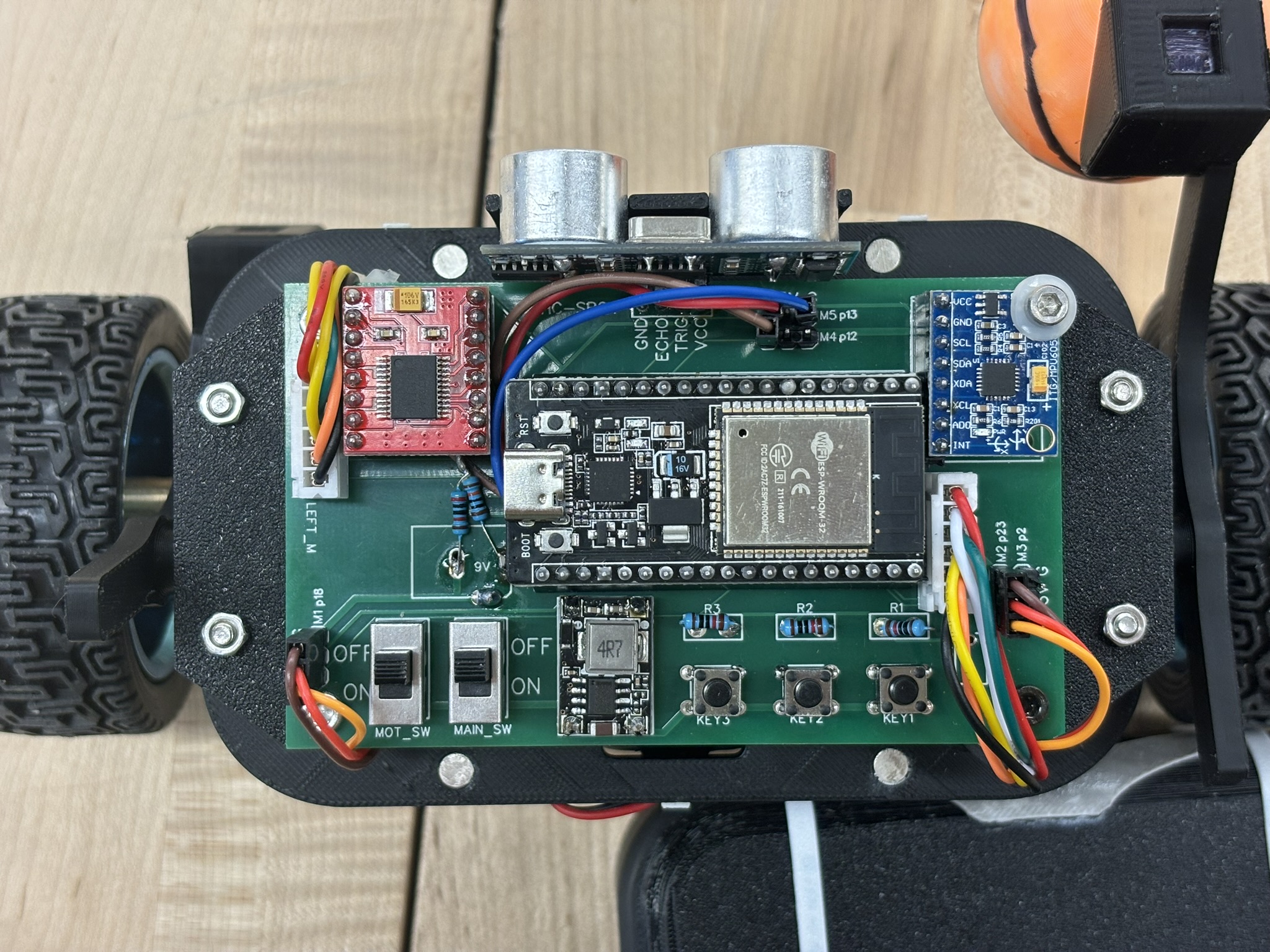
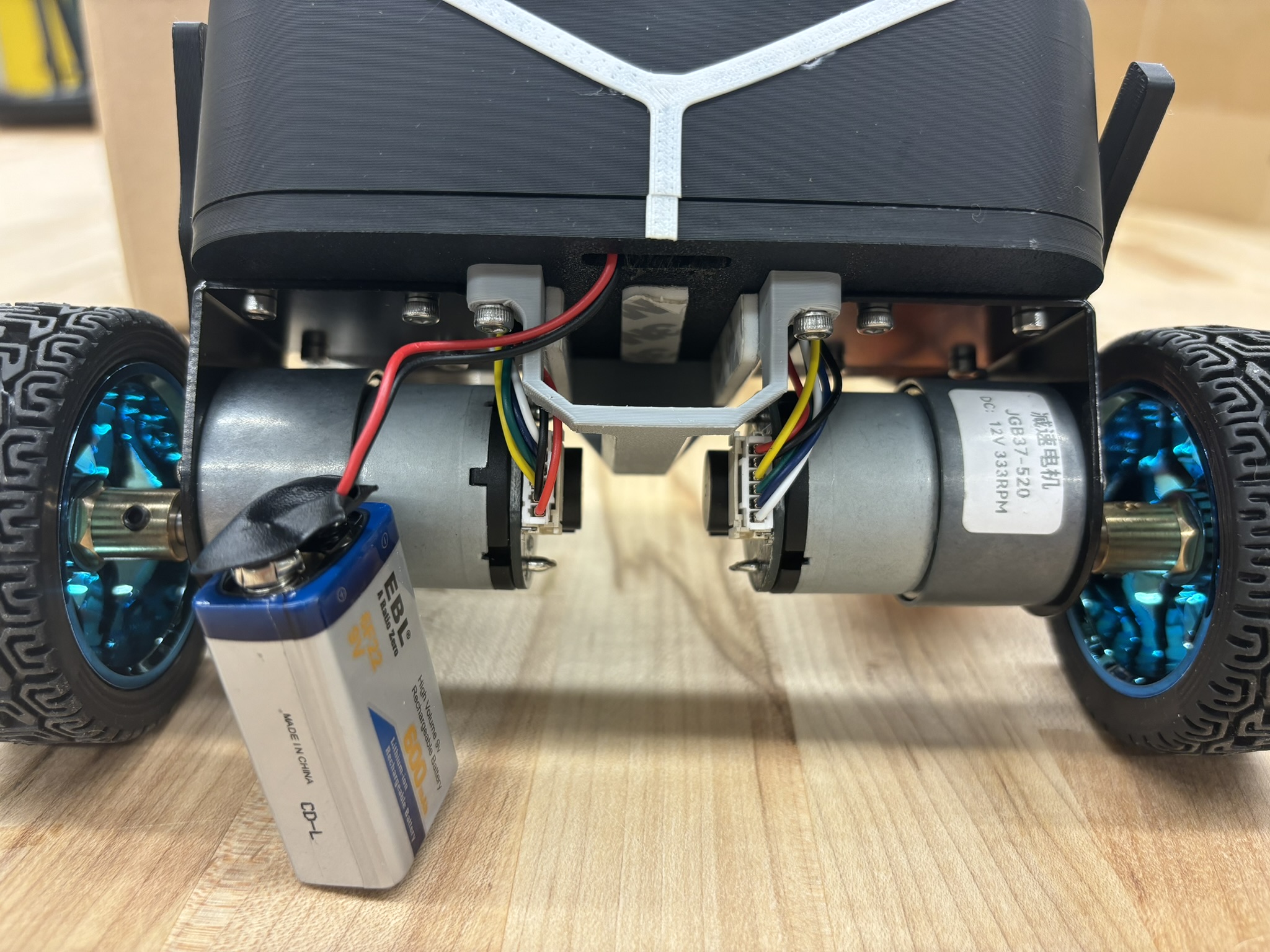
The first generation used the myRIO power system. A super large and heavy 3S Li-ion battery, two old super-large-friction motor with new encoders (old ones were broken), and a circuit board with two motor drives. ESP32 and MPU6050 were soldered onto the PCB breadboard. This whole setup was used in the ROS bot.
Since the friction of the motors was very large, the bot either behaved overshoot and divergence or overdamped and fell down, no matter how I tuned it.
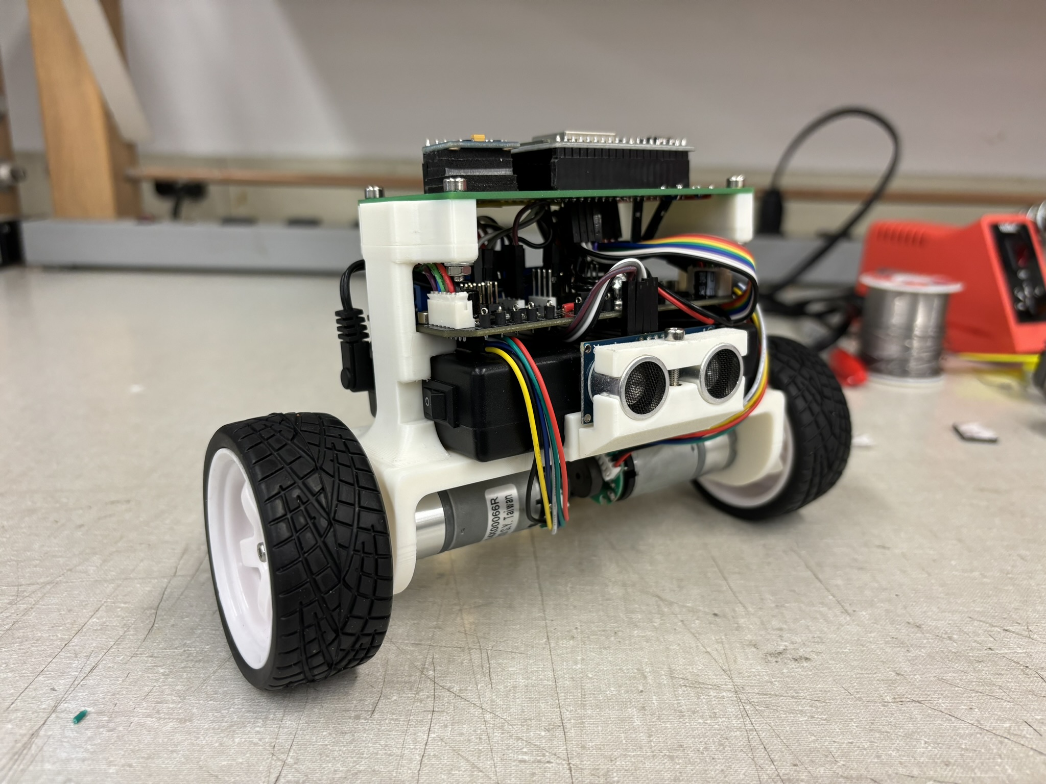
If the hardware is trash, there’s no way it’s gonna work.
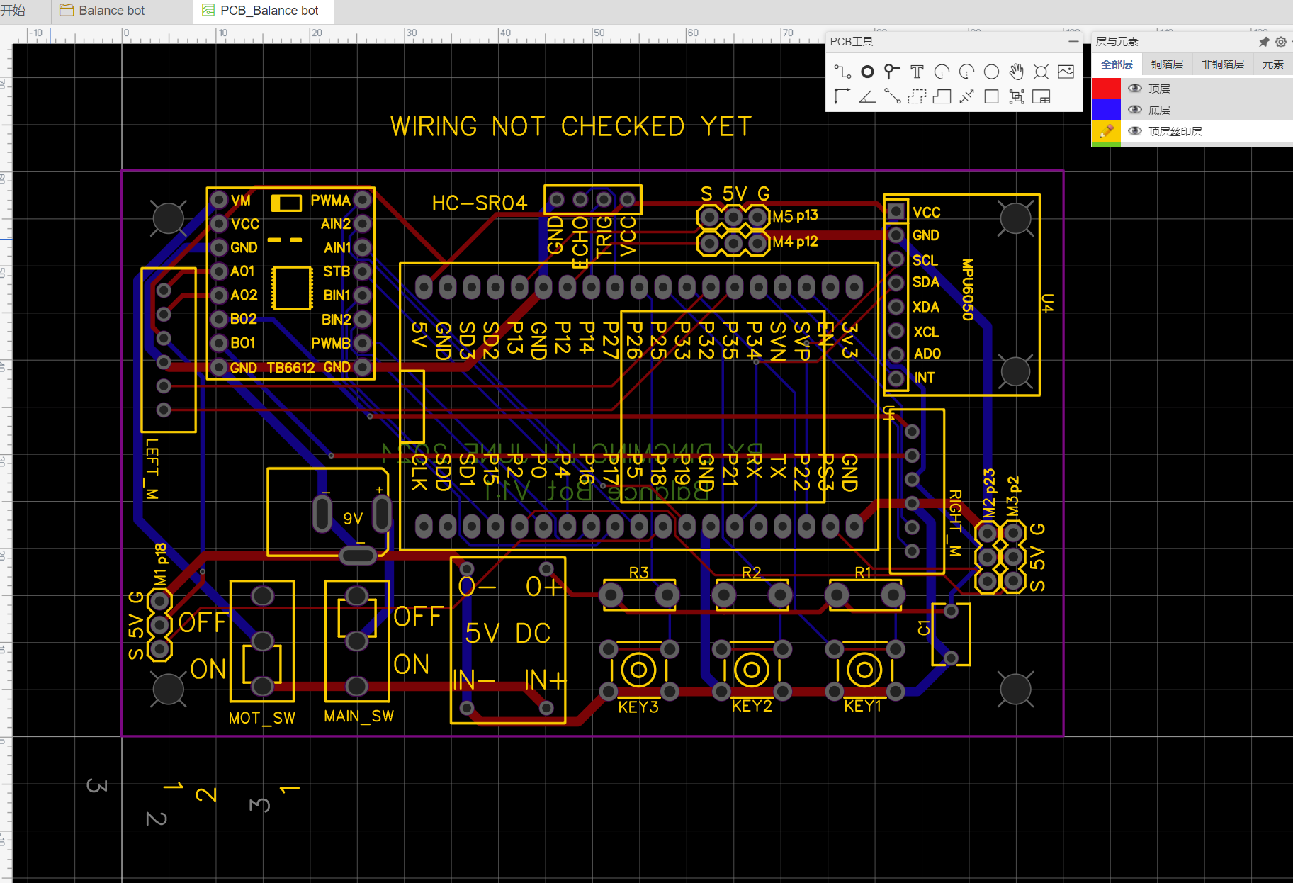
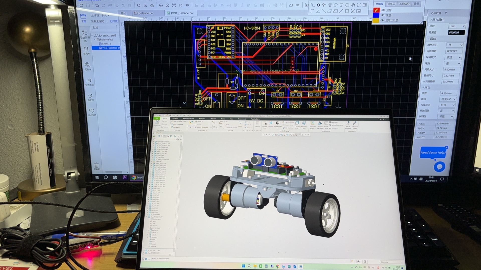
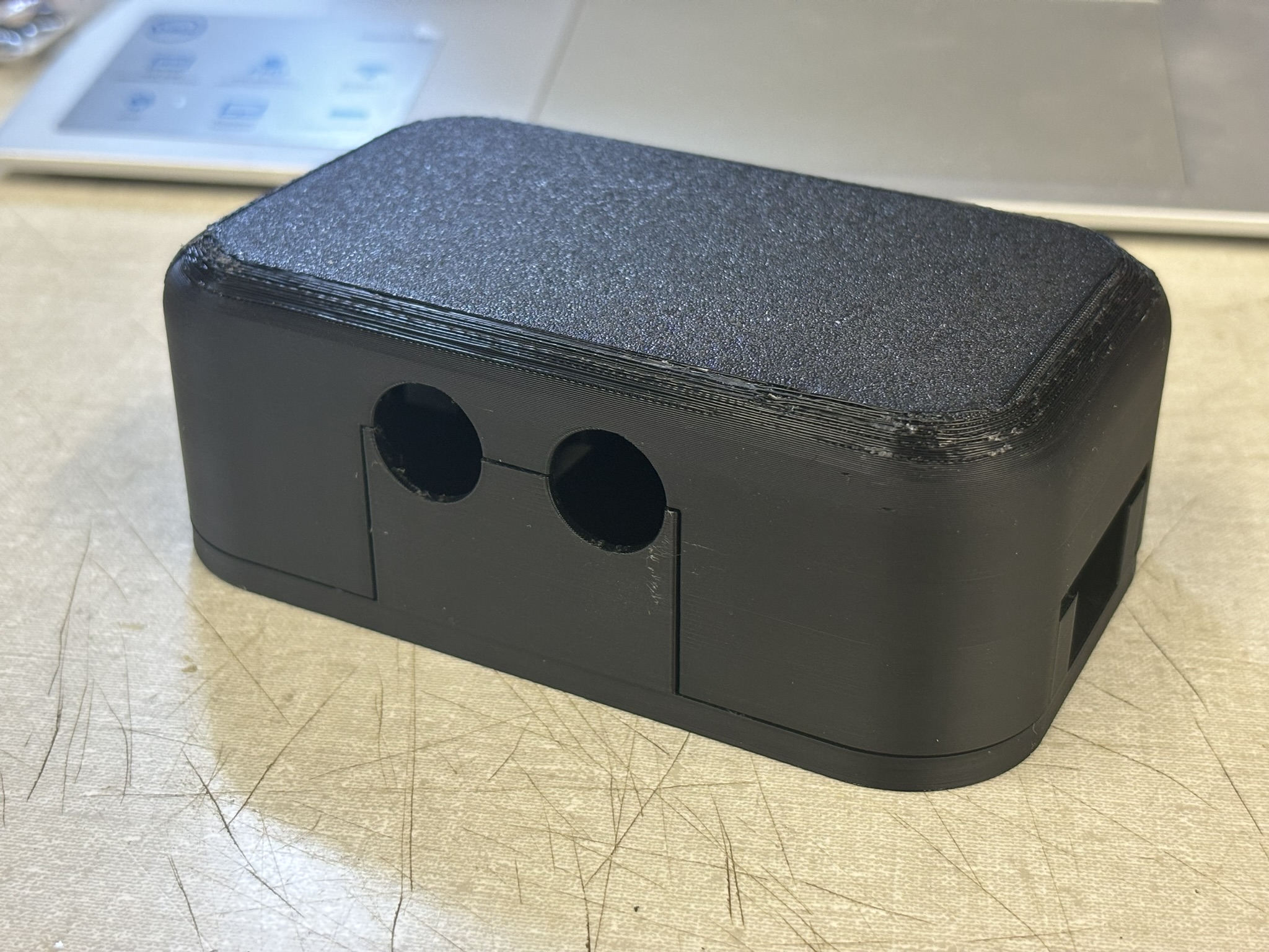
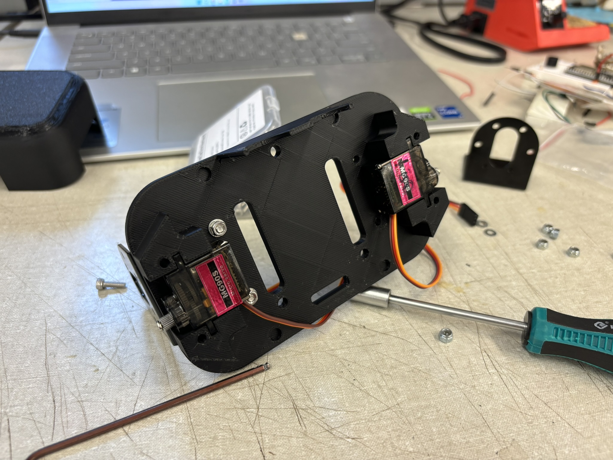
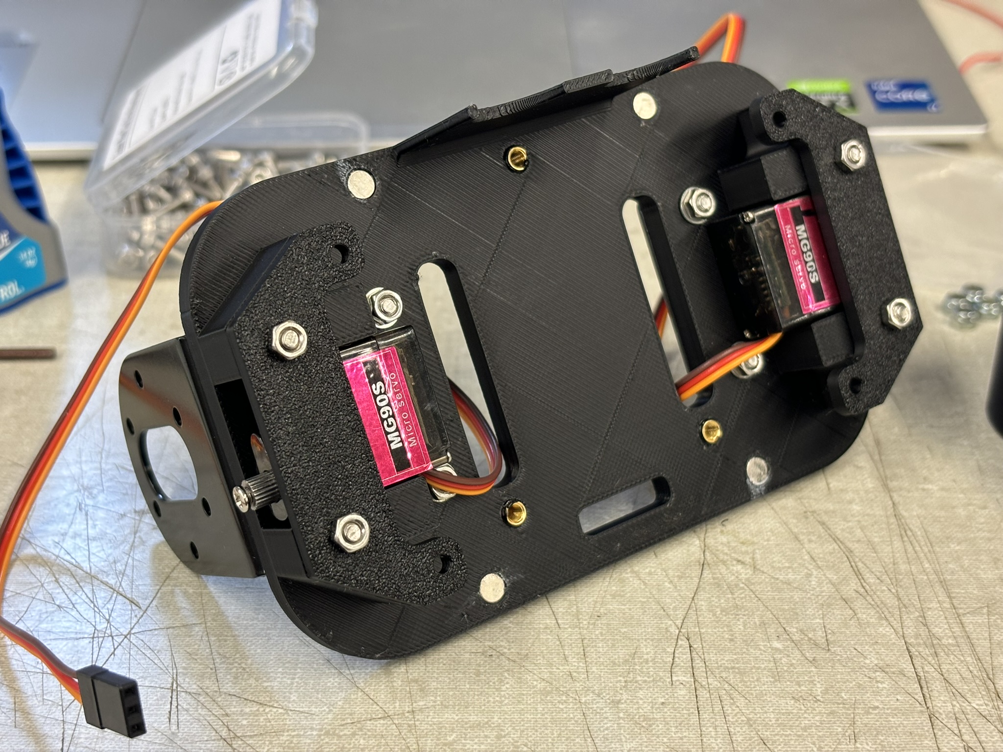
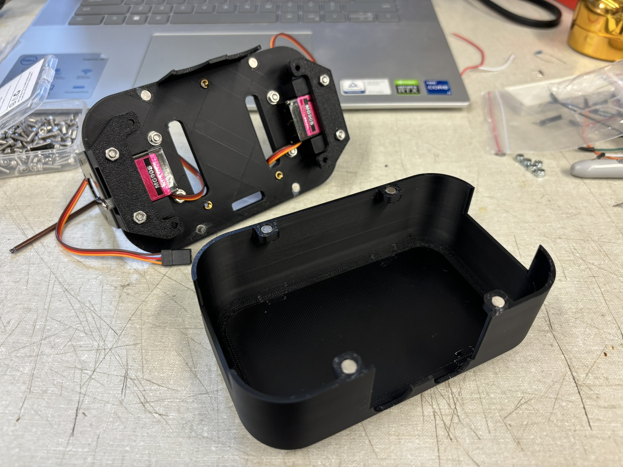
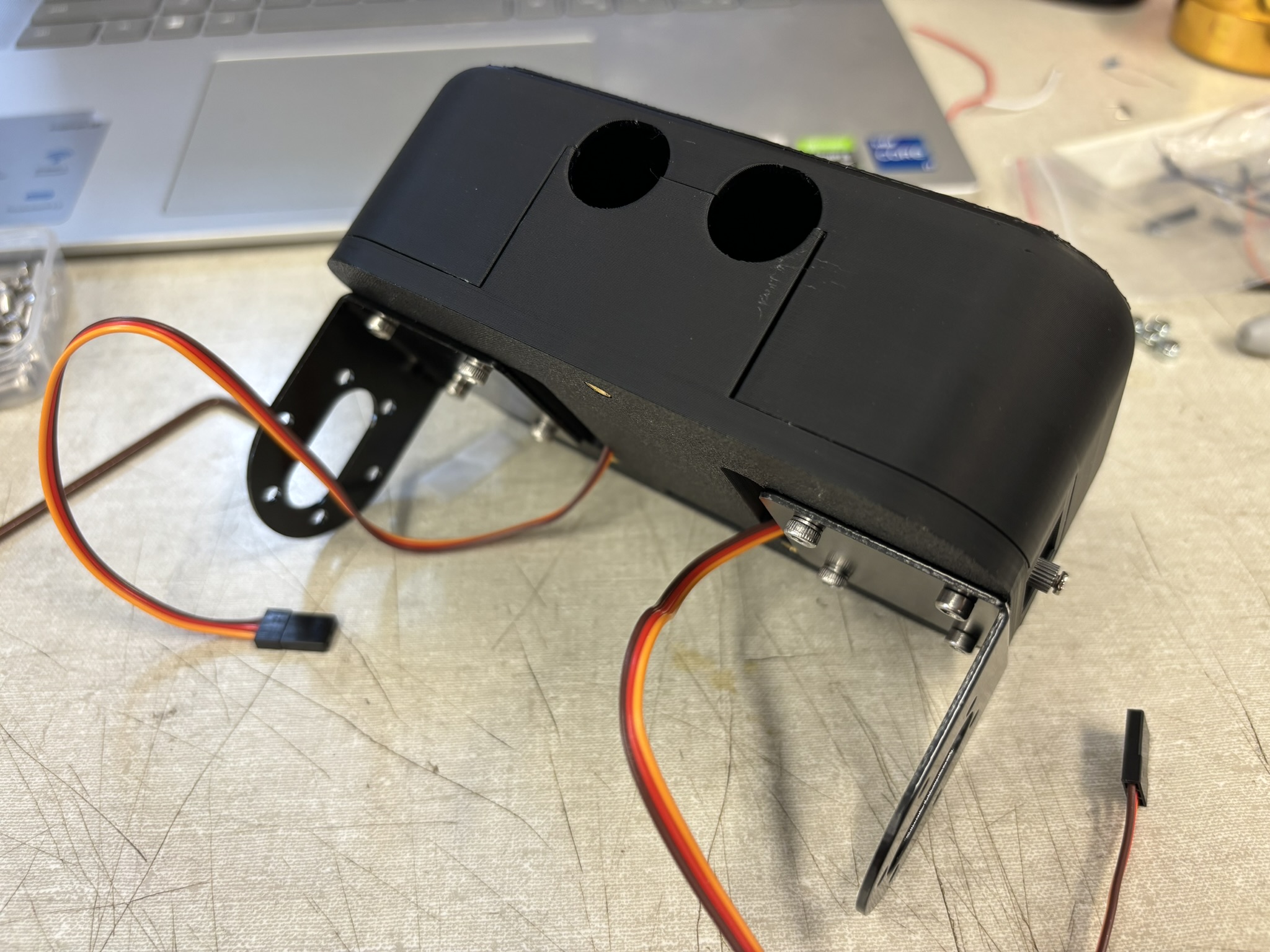
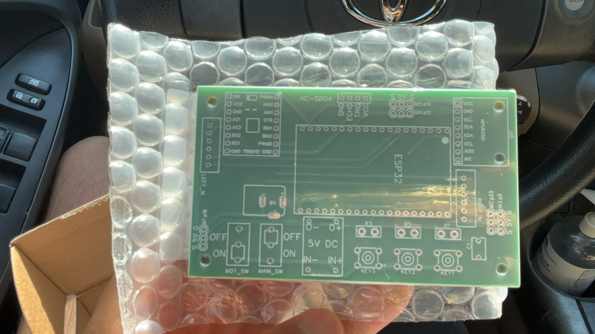
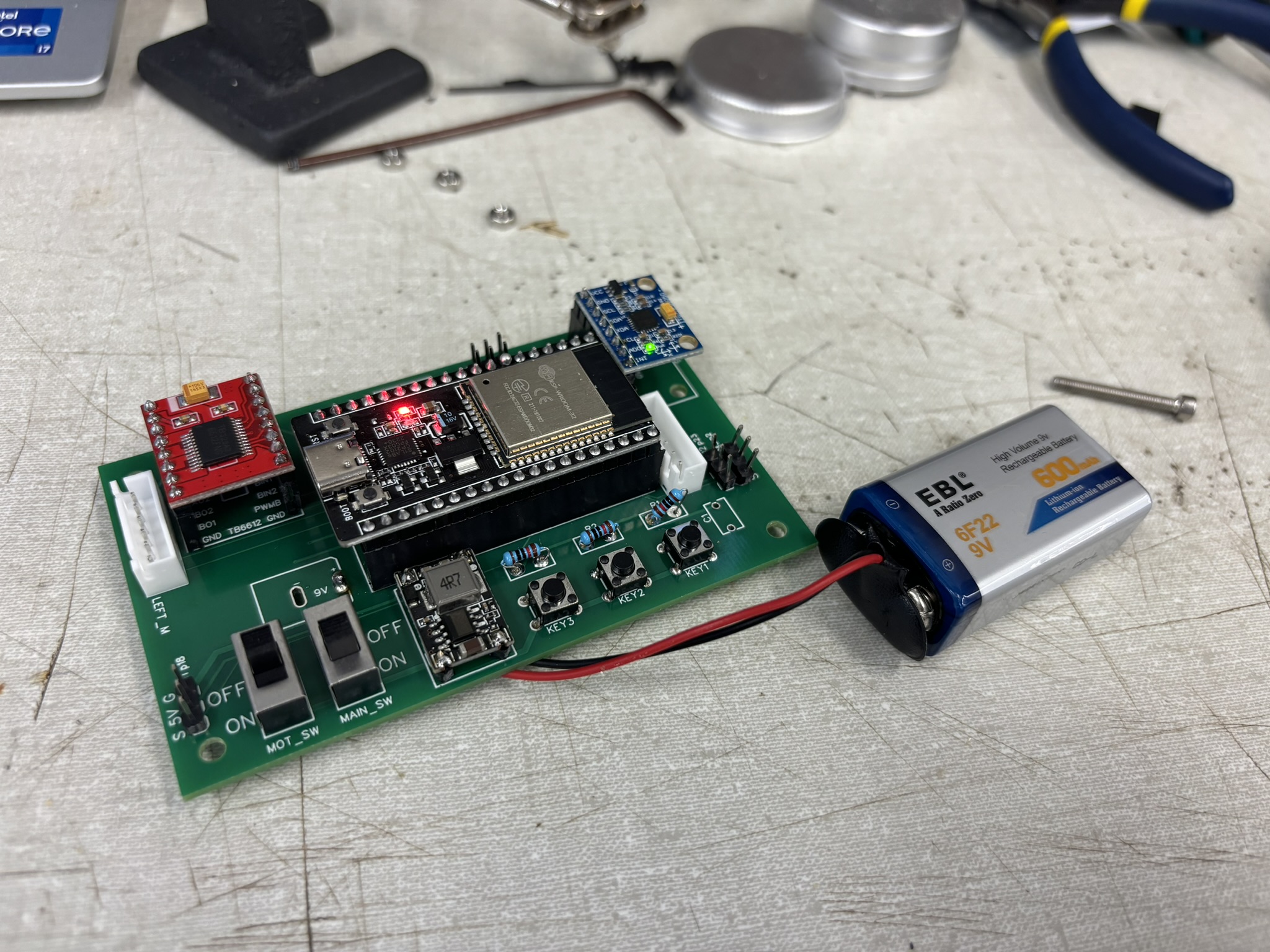
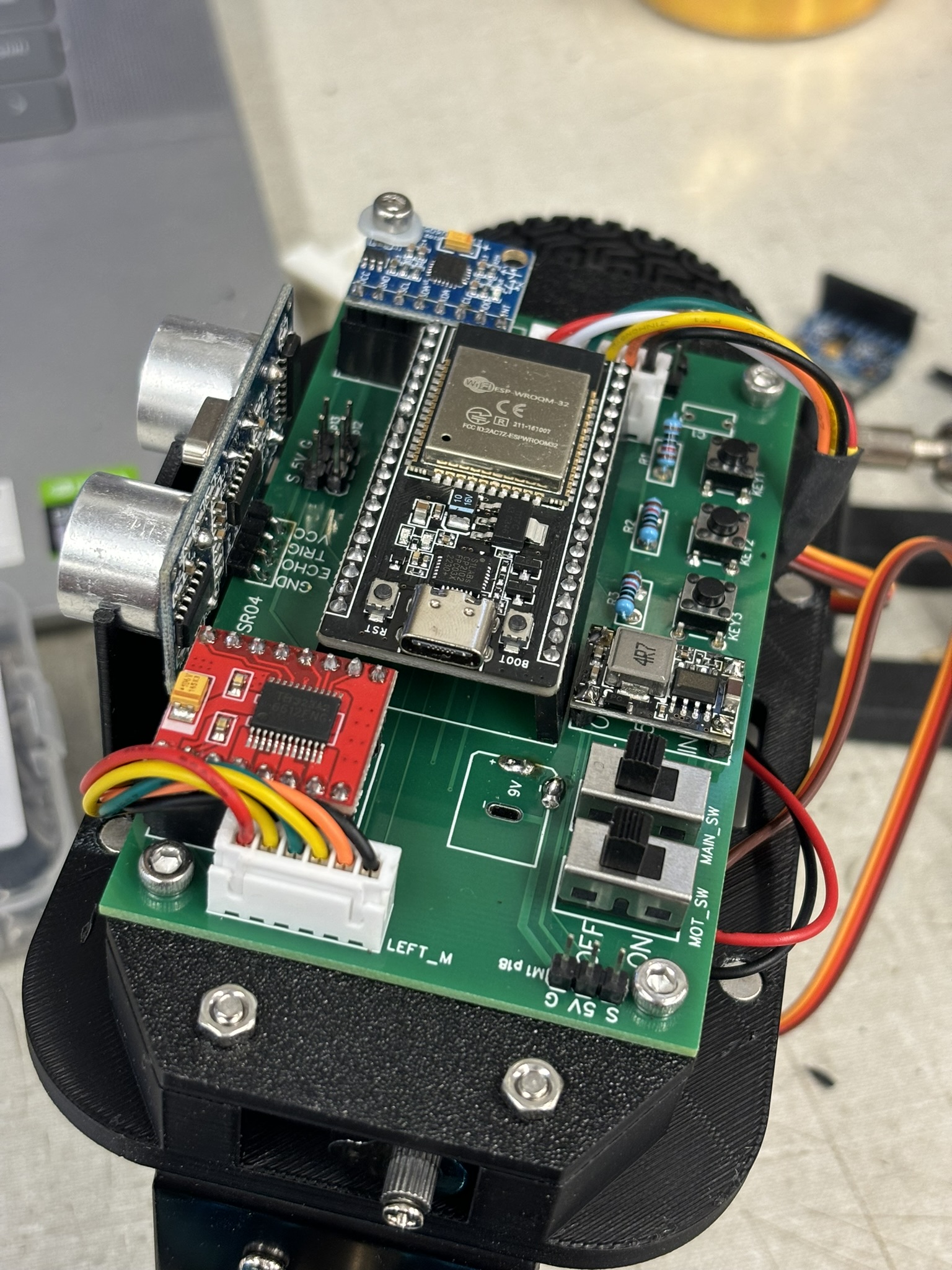
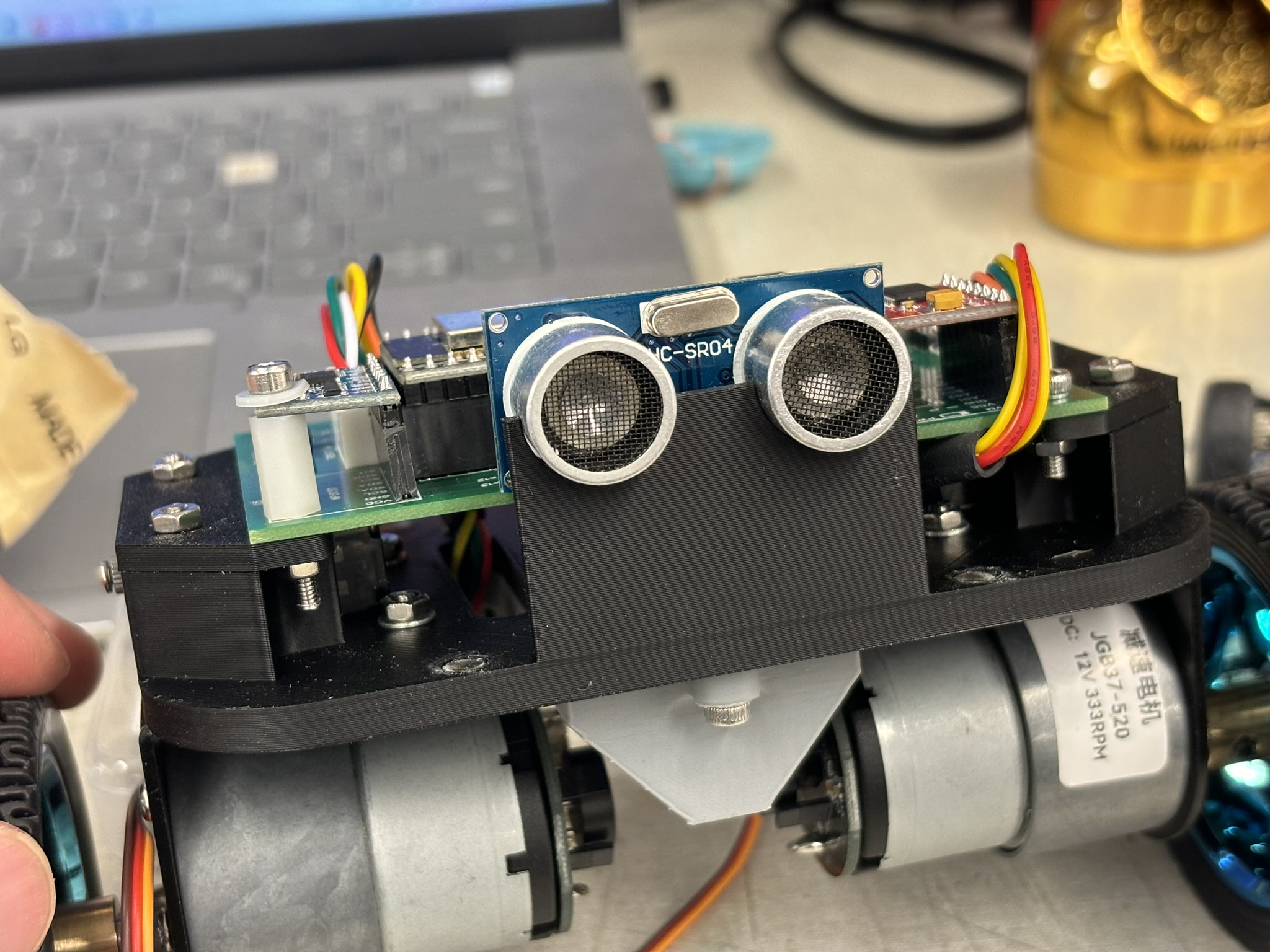
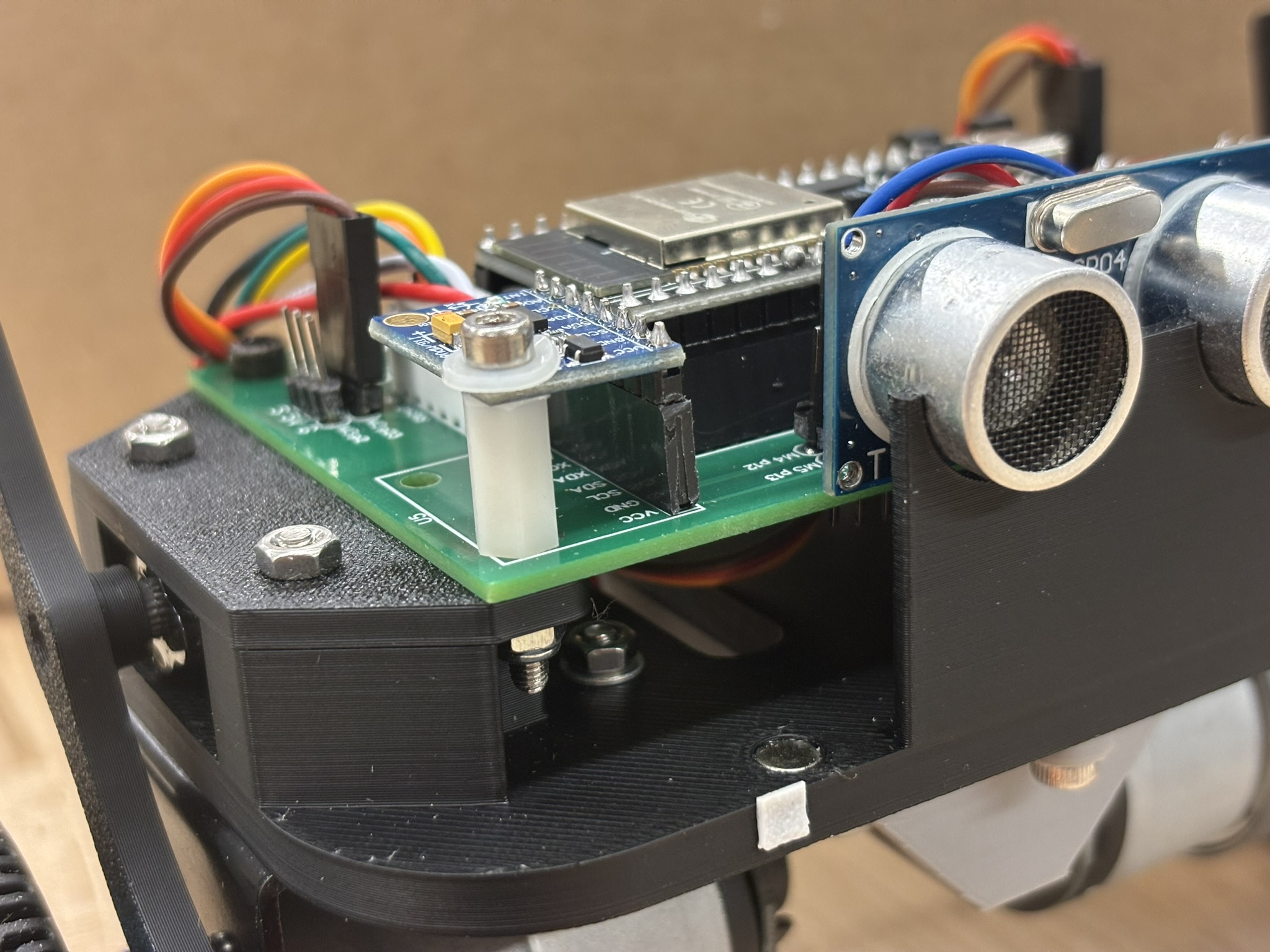
In summer, I built a much better one. The circuit was connected on a PCB, motor and motor drive were much better. The center of gravity was much lower, mass was lower, the height is lower, and the rotational inertia was much smaller. There were two ways to install the motor, one with a higher axel and one with a lower axel. The one with a higher axel can lower the CG a lot, and it should be easier to control, but what’s the fun of that configuration? Another configuration also worked for a lot of people, so I chose the one with higher CG.
This self balance bot used a cascade PID control system. The inner control loop is a PD control system for standing. The actual value comes from the pitch angle, and the error change comes from the pitch angular speed. Since the bot is an inverted pendulum, adding the integral to the standing control loop is pointless.
The outer loop is a PI control system for wheel speed. The actual value comes from the 10 times the sum of the two encoder values after a complementary filter. The output value of this controller is the input value of the PD controller.
