Personal Project: ROS Bot

I. Intro

Date: May – June 2024

Codes are on github, click here.

It took me several days to install Ubuntu on Raspberry pi 4B. The main issue was there were no displays on the monitors, so I don’t know if it’s because of the cable, the sd card, or the image. I tried formatting different sd cards with different methods, and etching the image from different sources to different sd cards with different etching software. After I tried on two TVs and two PC monitors, finally the last one worked. The following code is what I figured out for three days. 1080p doesn’t work with my monitor, it flashes constantly, so I had to use 720p.

[all]
kernel=vmlinuz
cmdline=cmdline.txt
initramfs initrd.img followkernel

[pi4]
max_framebuffers=2
arm_boost=1


[all]
# Enable the audio output, I2C and SPI interfaces on the GPIO header. As these
# parameters related to the base device-tree they must appear *before* any
# other dtoverlay= specification
dtparam=audio=on
dtparam=i2c_arm=on
dtparam=spi=on

# Comment out the following line if the edges of the desktop appear outside
# the edges of your display
#disable_overscan=1
#overscan_left=20
#overscan_right=20
#overscan_top=20
#overscan_bottom=20


# If you have issues with audio, you may try uncommenting the following line
# which forces the HDMI output into HDMI mode instead of DVI (which doesn't
# support audio output)
# hdmi_safe=1
hdmi_drive=2
hdmi_force_hotplug=1
hdmi_ignore_edid=0xa5000080
hdmi_group=2
hdmi_mode=85
config_hdmi_boost=11


[cm4]
# Enable the USB2 outputs on the IO board (assuming your CM4 is plugged into
# such a board)
#dtoverlay=dwc2,dr_mode=host

[all]

# Enable the KMS ("full" KMS) graphics overlay, leaving GPU memory as the
# default (the kernel is in control of graphics memory with full KMS)
# dtoverlay=vc4-kms-v3d

# Autoload overlays for any recognized cameras or displays that are attached
# to the CSI/DSI ports. Please note this is for libcamera support, *not* for
# the legacy camera stack
camera_auto_detect=1
display_auto_detect=1

# Config settings specific to arm64
arm_64bit=1
dtoverlay=dwc2

I don’t remember which etching software and image I used for Ubuntu 23 because the last ROS version only works on Ubuntu 20 and I had to reinstall Ubuntu 20.04 server version! And then somehow I installed the desktop to the server version (followed in this link).

Then it took me another 16 days to learn ROS, from topic to SLAM.

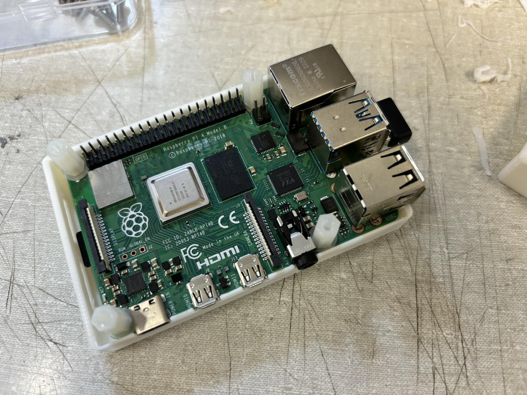
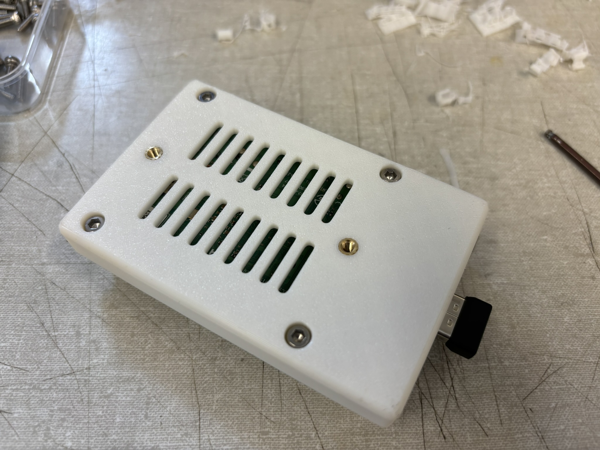
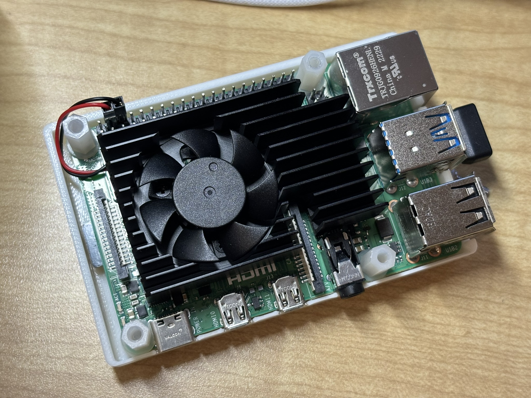
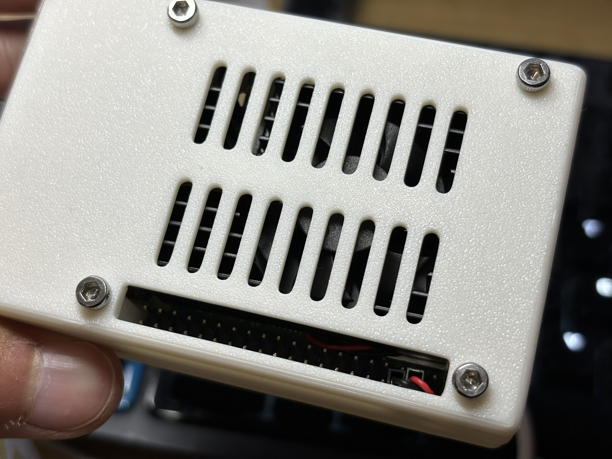
II. Build a Case for PI4B
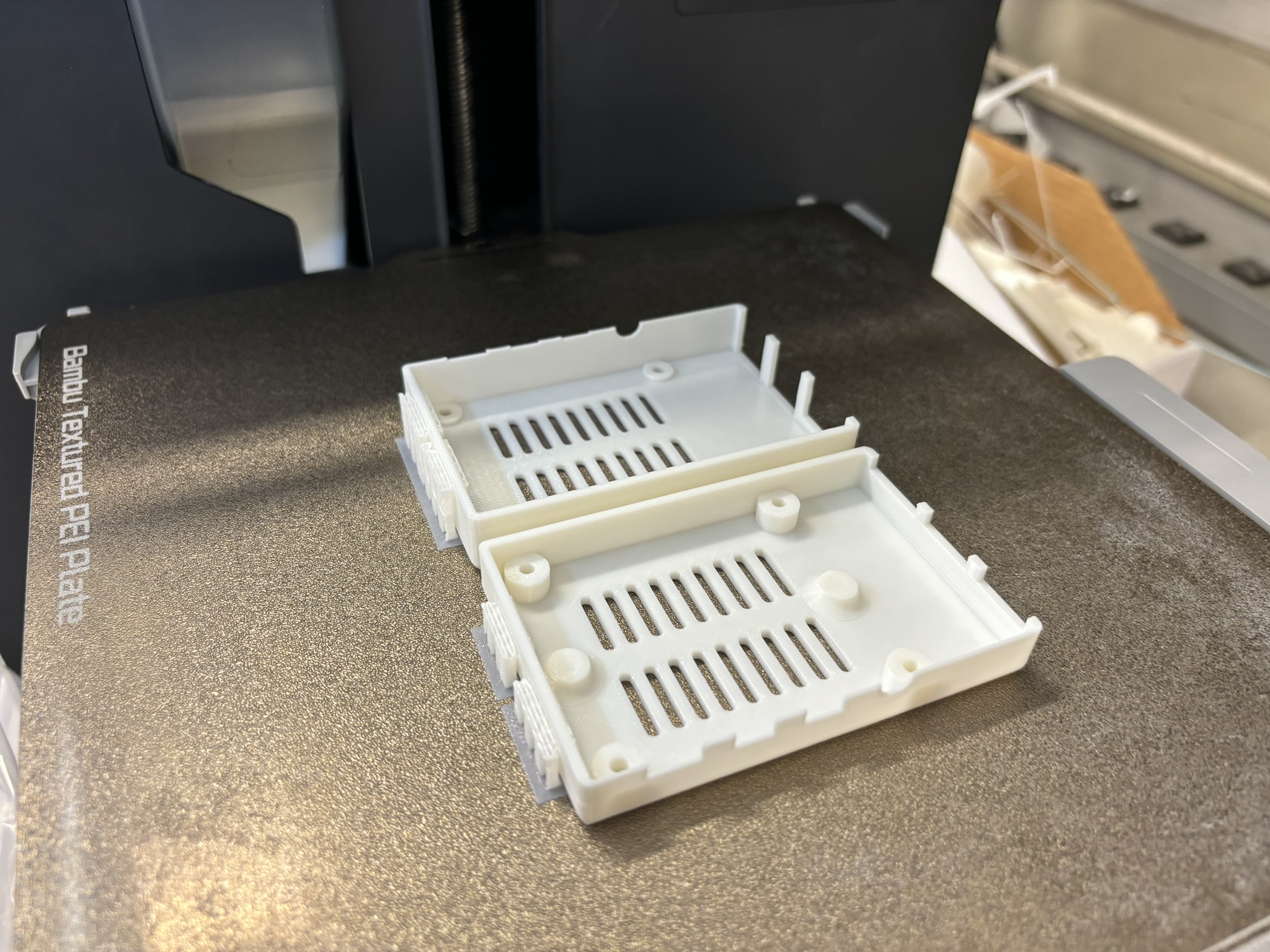
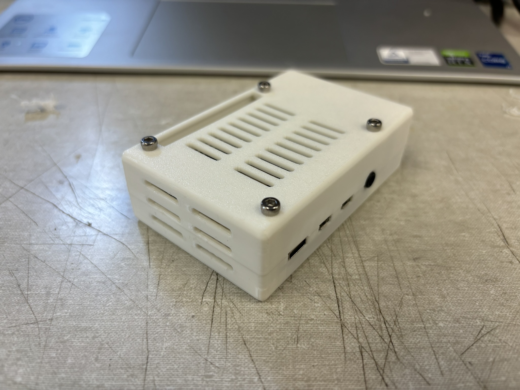
Figure 1: Designed and print the case for Pi4B
Figure 2: put Pi4B in there
Figure 3: four bolts and nylon hex spacers secure the board to the case. Two threaded insert were designed for future use.
Figure 4: cooling fan arrived. It fit perfectly in the board and case because its height is smaller than the highest point of Pi4B
Figure 5: the power of the fan was connected to the 5V and GND on Pi4B
Figure 6: final assembly

III. ROS Learning

It took me about three days to figure out how to communicate between Arduino and ROS. All materials are on github, and my notes contain the question I encounter and their solutions.
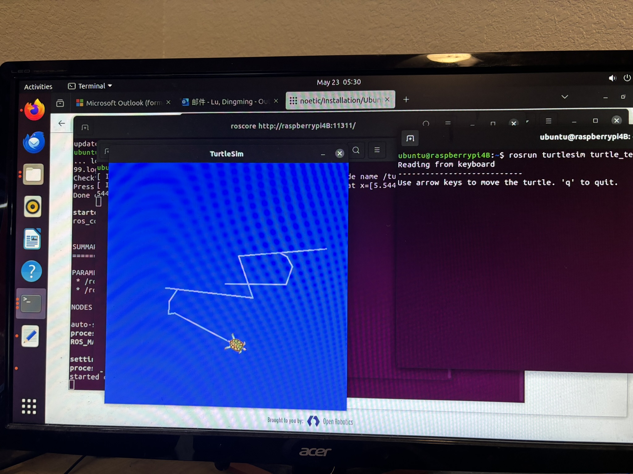
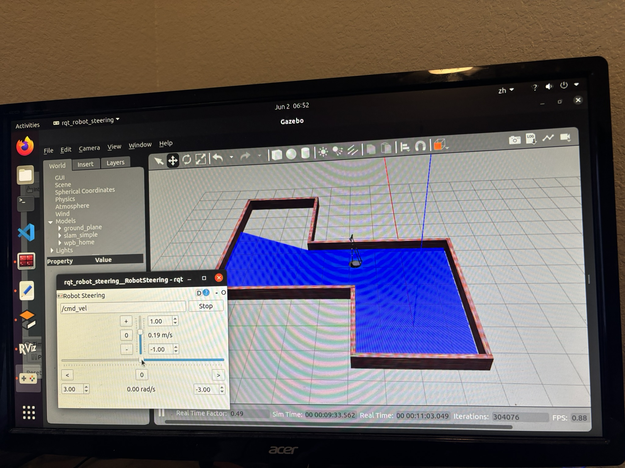
Figure 7: turtle simulation worked, it means ROS worked
Figure 8: learning SLAM with Gazebo, but the fram rate drops below 10. Pain
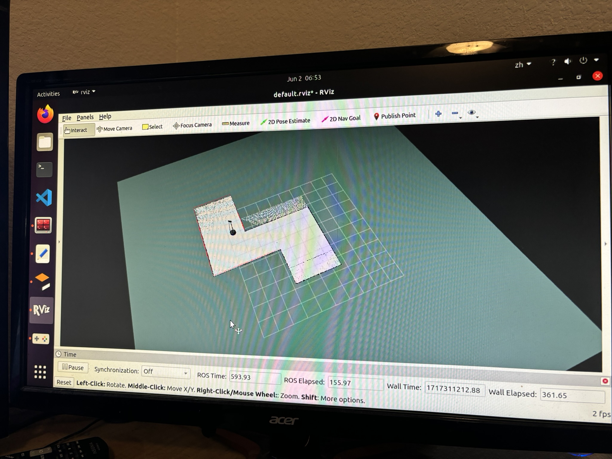
Figure 9: the map was displayed in rviz
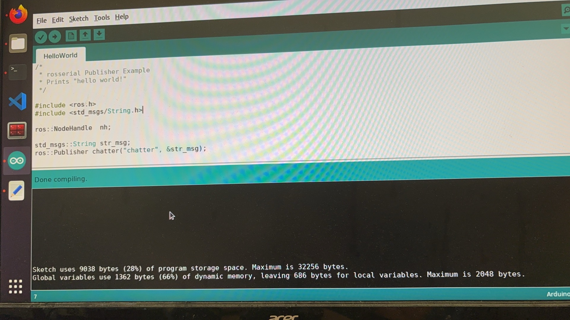
Figure 10: learning how to setup communication between Arduino and ROS with rosserial. I can only install Arduino IDE 1.8 on Uubntu 20.04, and the compiling is a little different than Arduino IDE 2.3, so later on I only use 2.3 on my laptop.
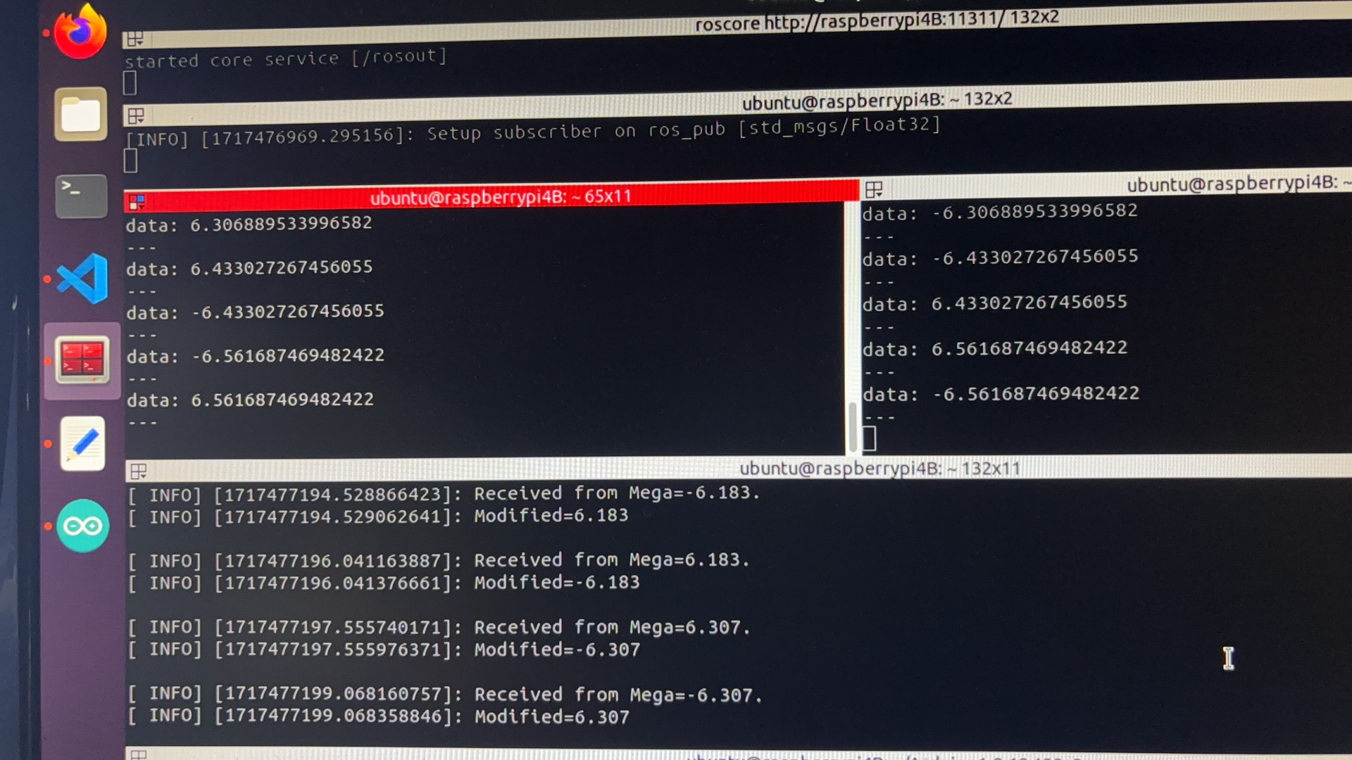
Figure 11: testing communication

IV. Building the ROS Bot

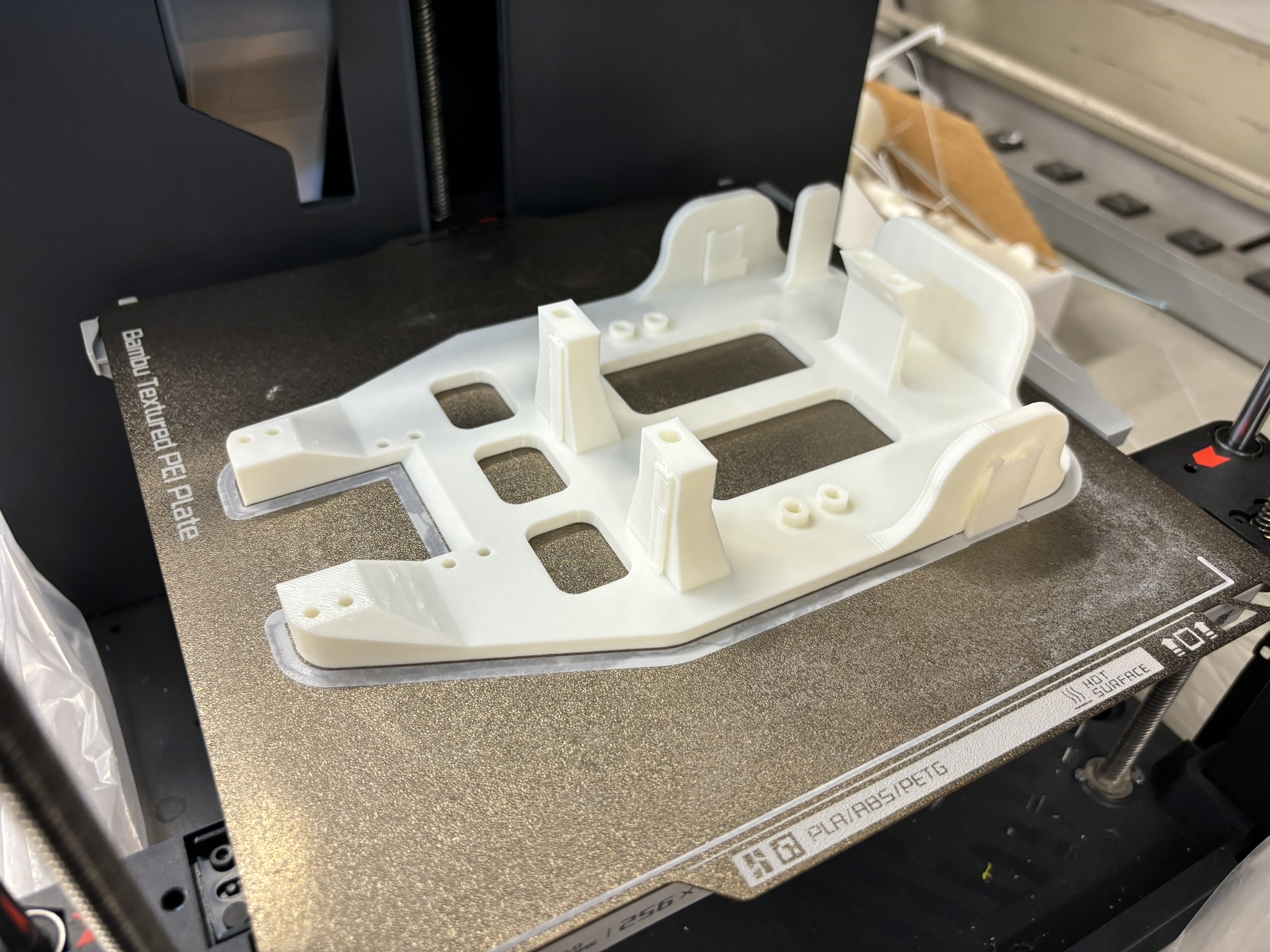
Figure 12: printing the chassis
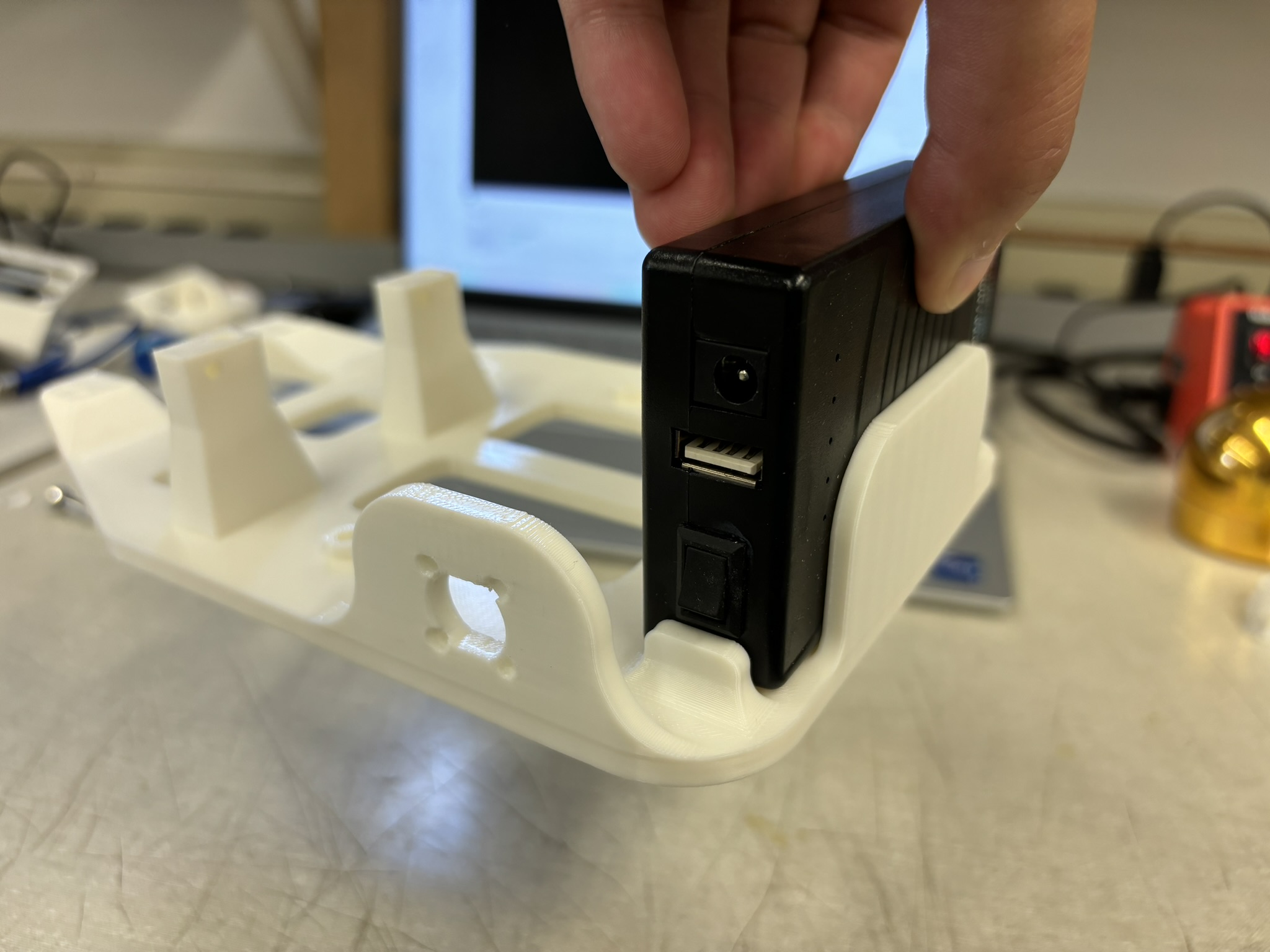
Figure 13: the tolerance is perfect. The friction is just enough to slide it in and not letting it move around
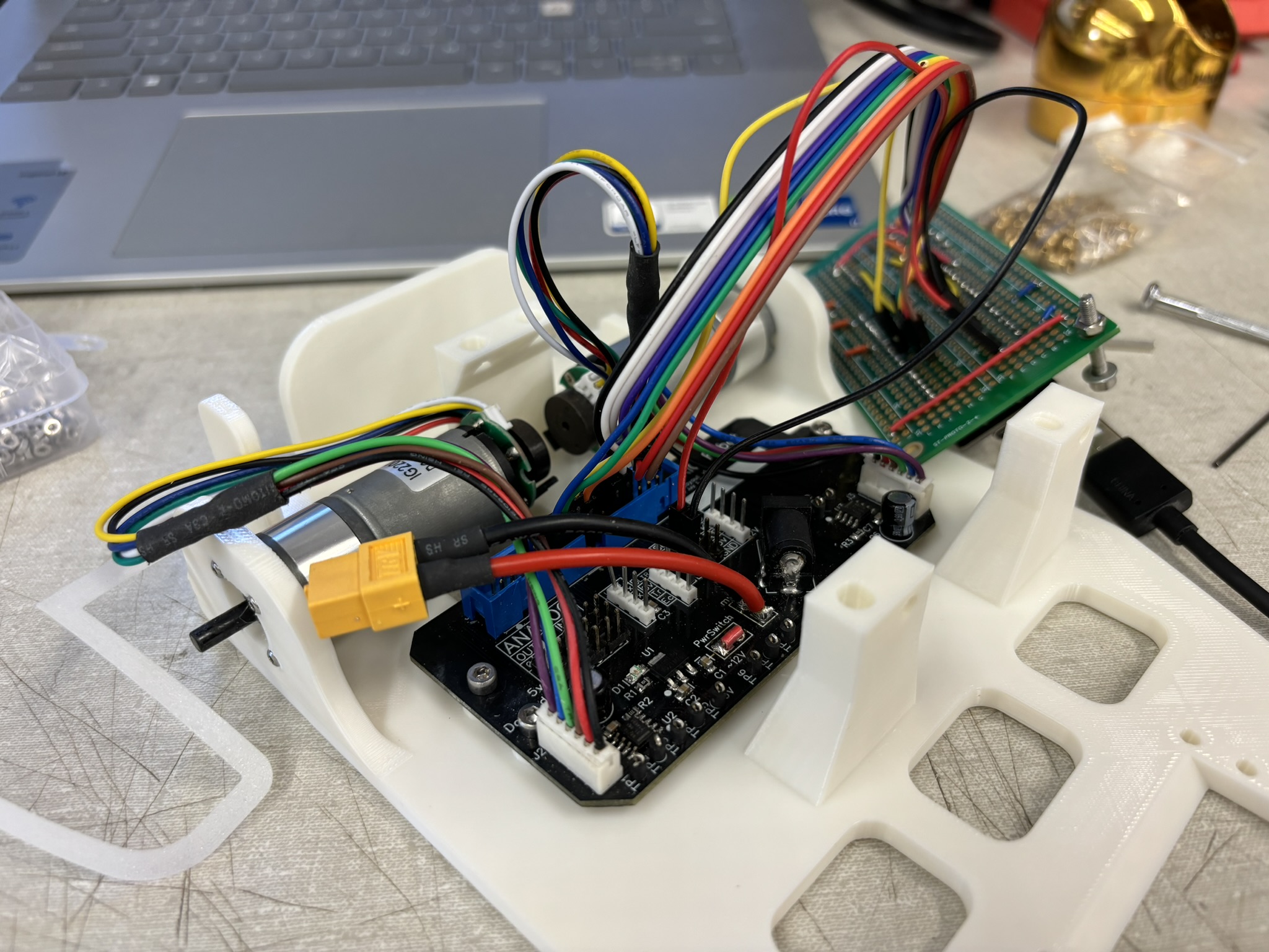
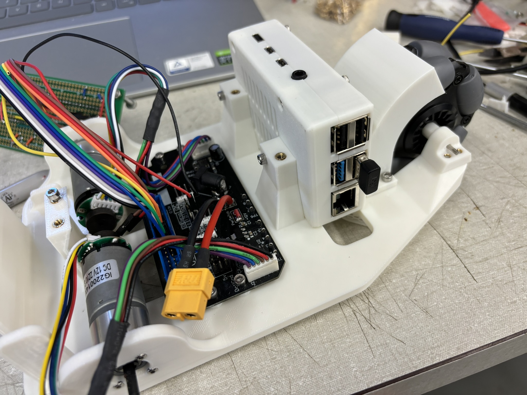
Figure 14: install the motor drive and motors
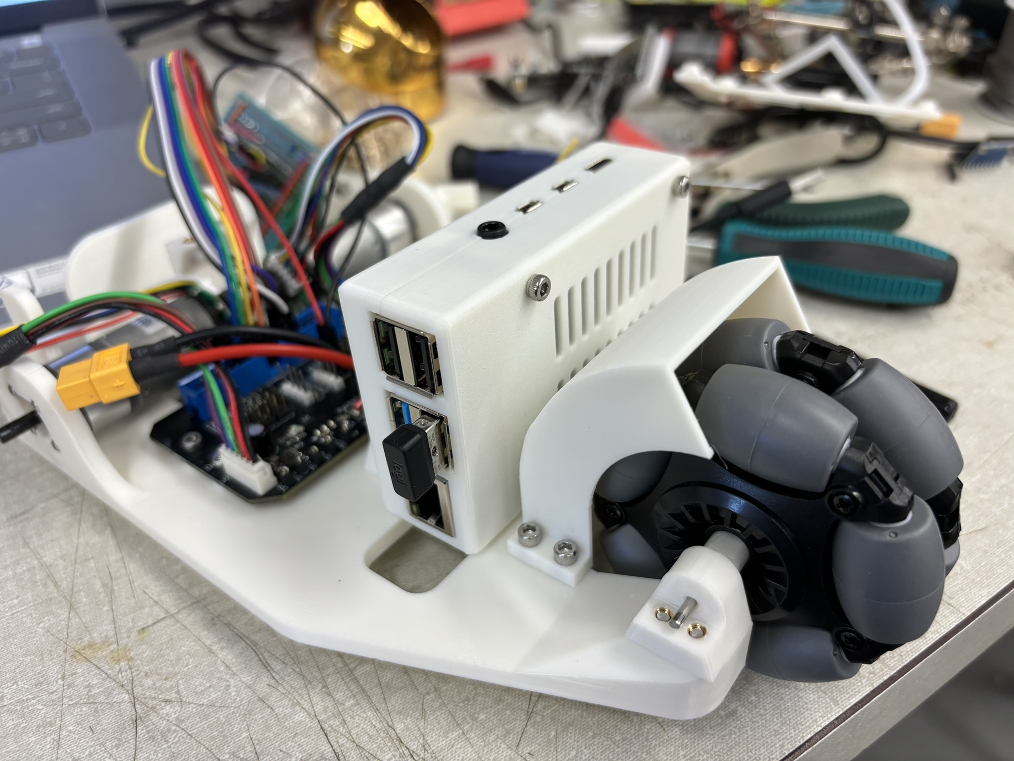
Figure 15: install Pi4B
Figure 16: using two threaded inserts to secure the Pi4B
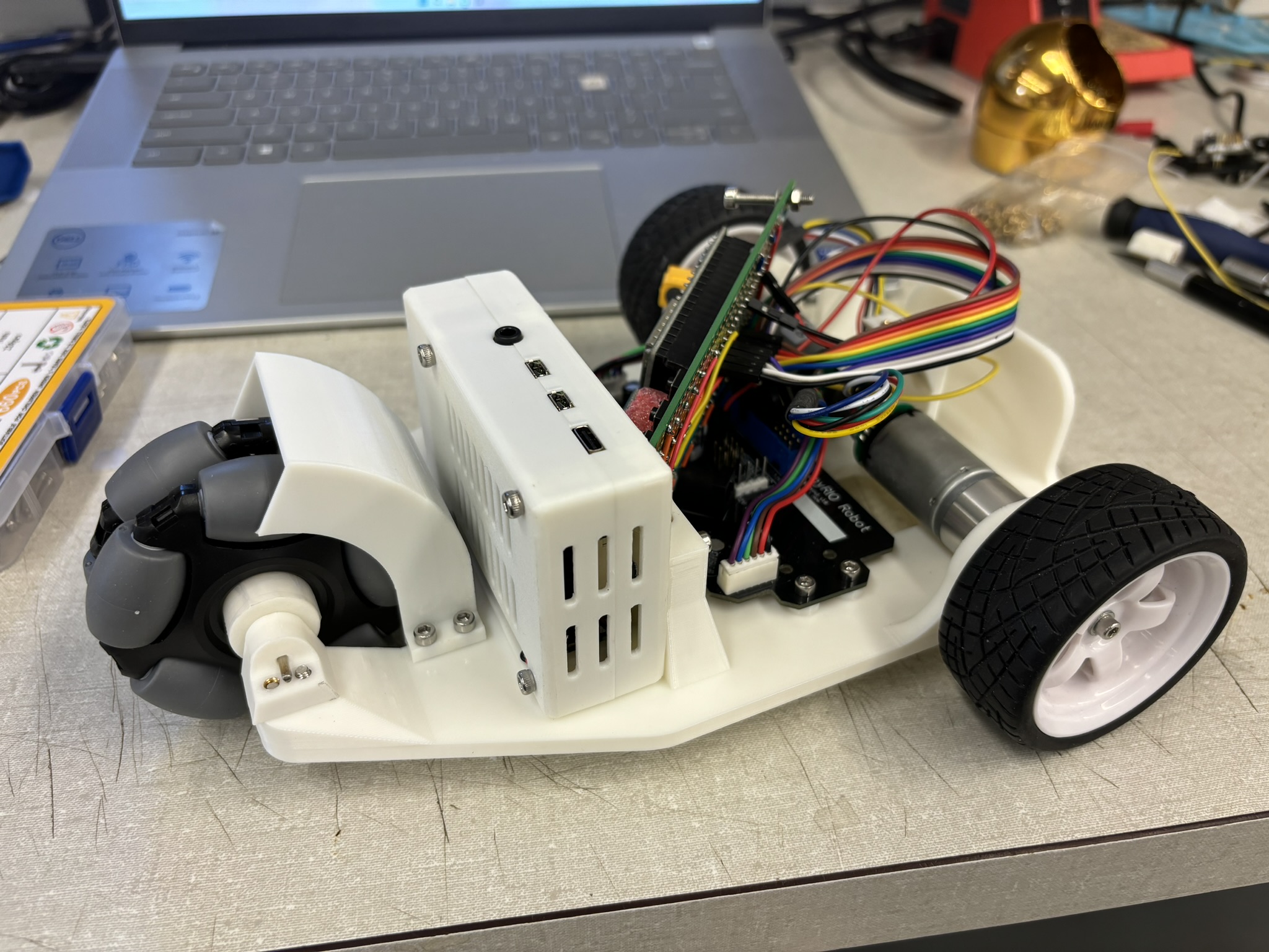
Figure 17: Also install the front wheel
Figure 18: install the upper deck and other electronics
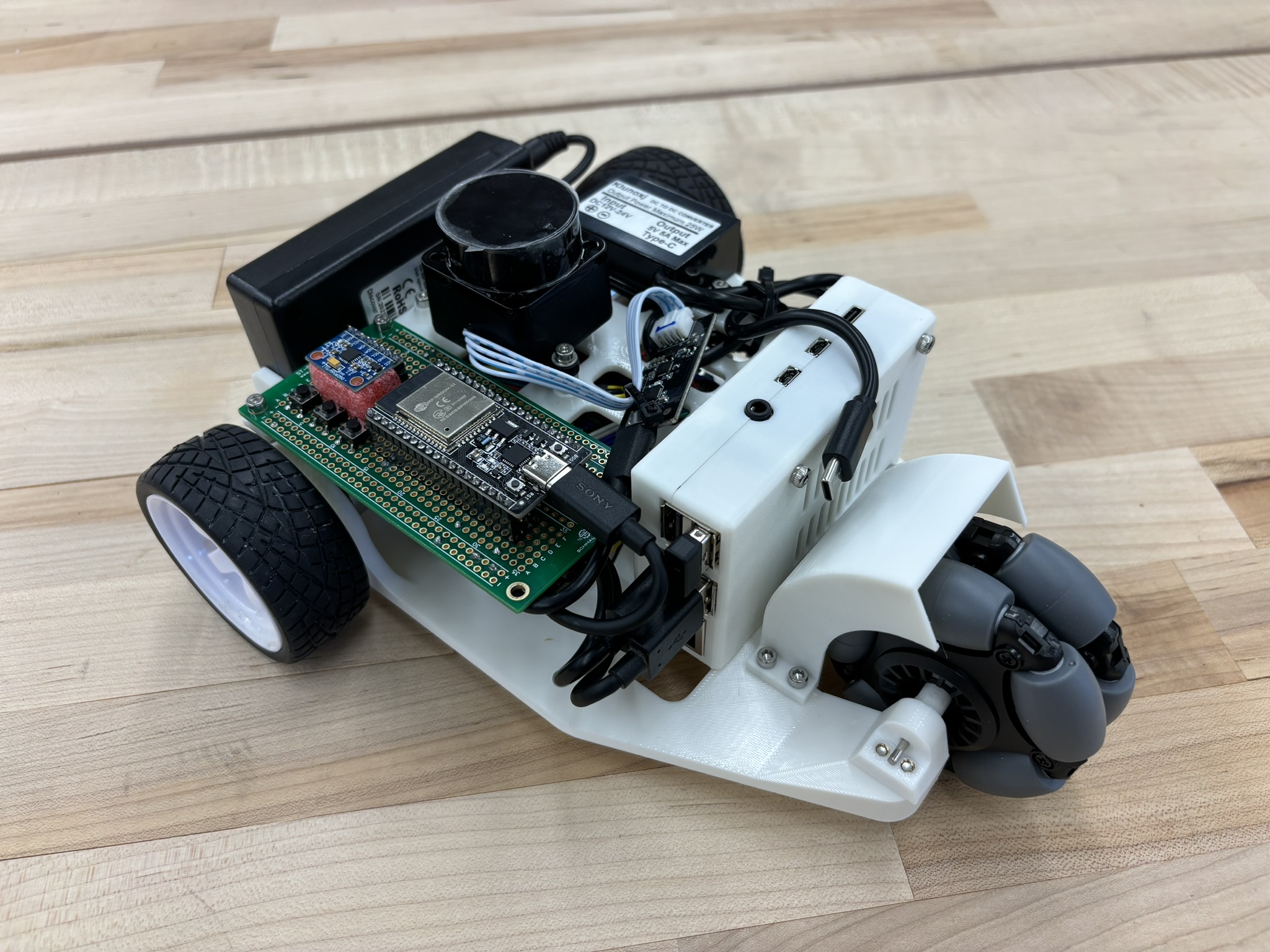
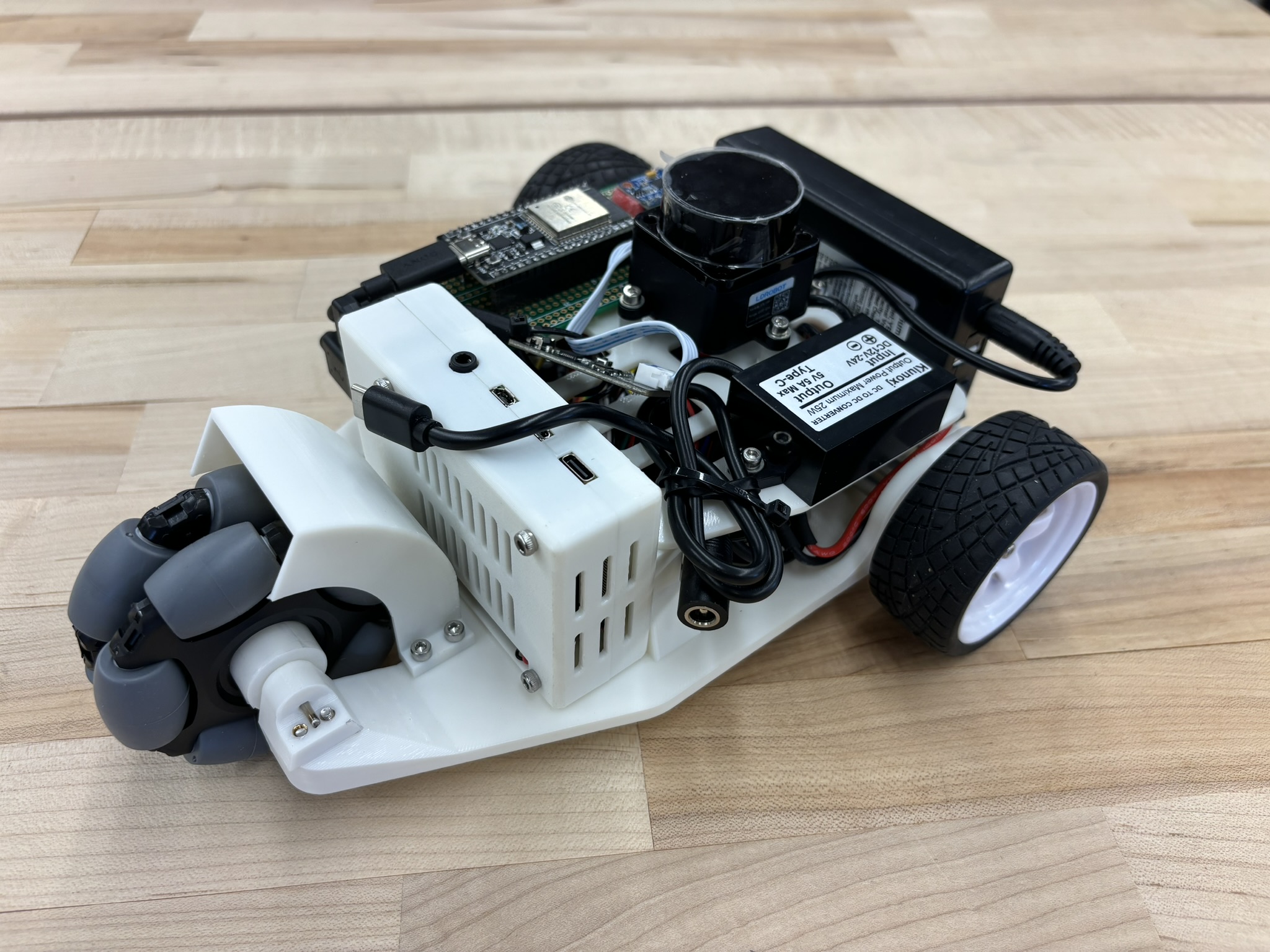
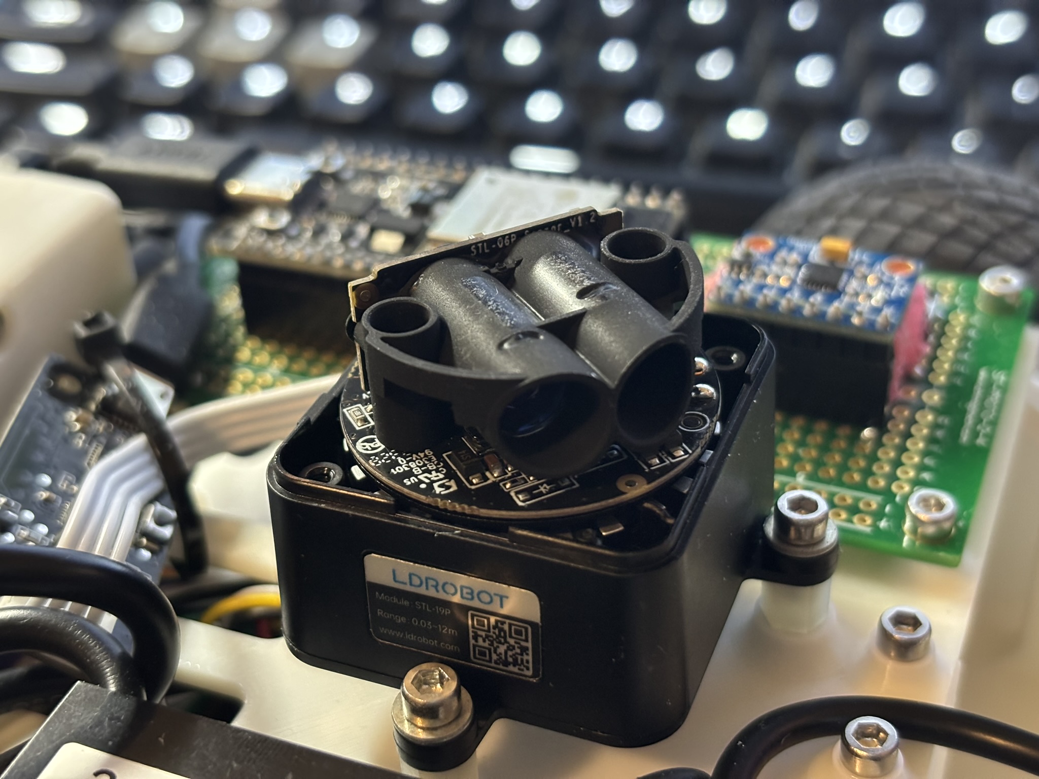
Figure 19: Everything left is just the 90 degrees type-C adapter so the power cable won’t block the LiDAR. LiDAR was designed to be below 100 mm in height.
Figure 20: I built a simple code so I can control it with bluetooth, and it has a simple PD controller for yaw control
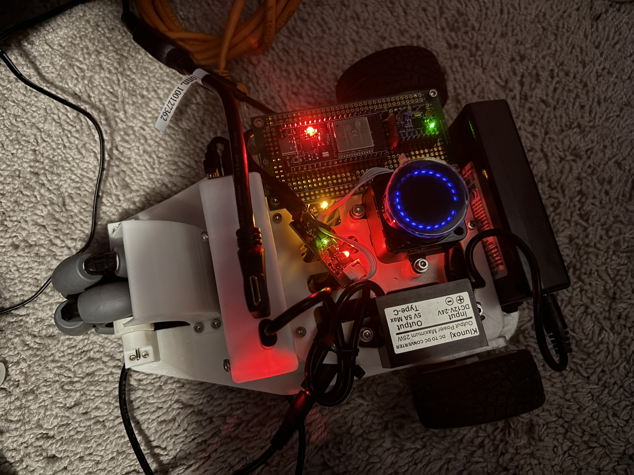
Figure 21: power everything up. That’s a lot of LEDs

V. SLAM and My Apartment

ROS has a sample odometry code, so I modified it.
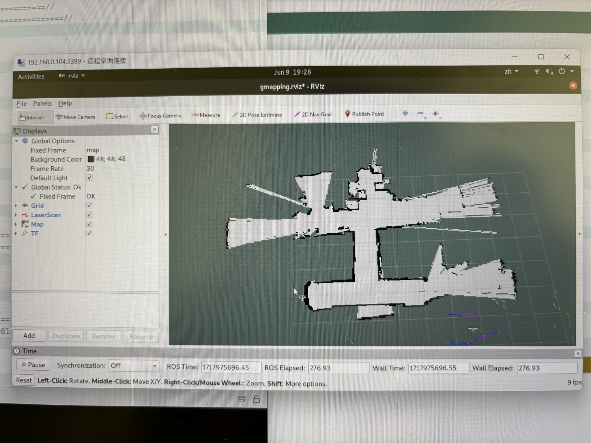
Figure 22: testing odometry
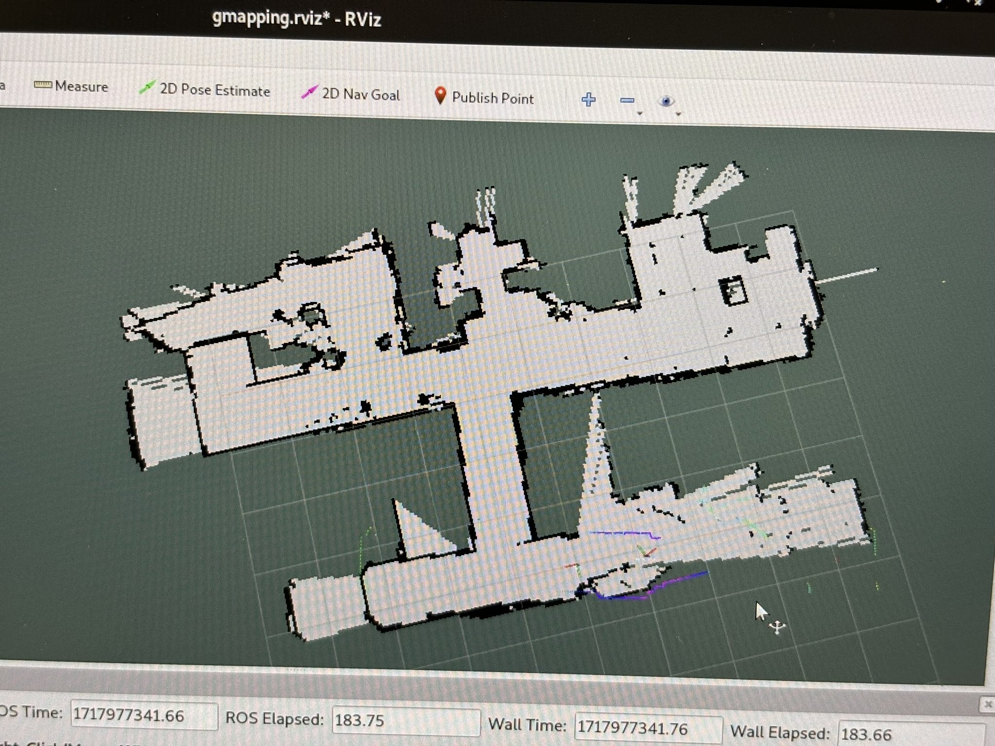
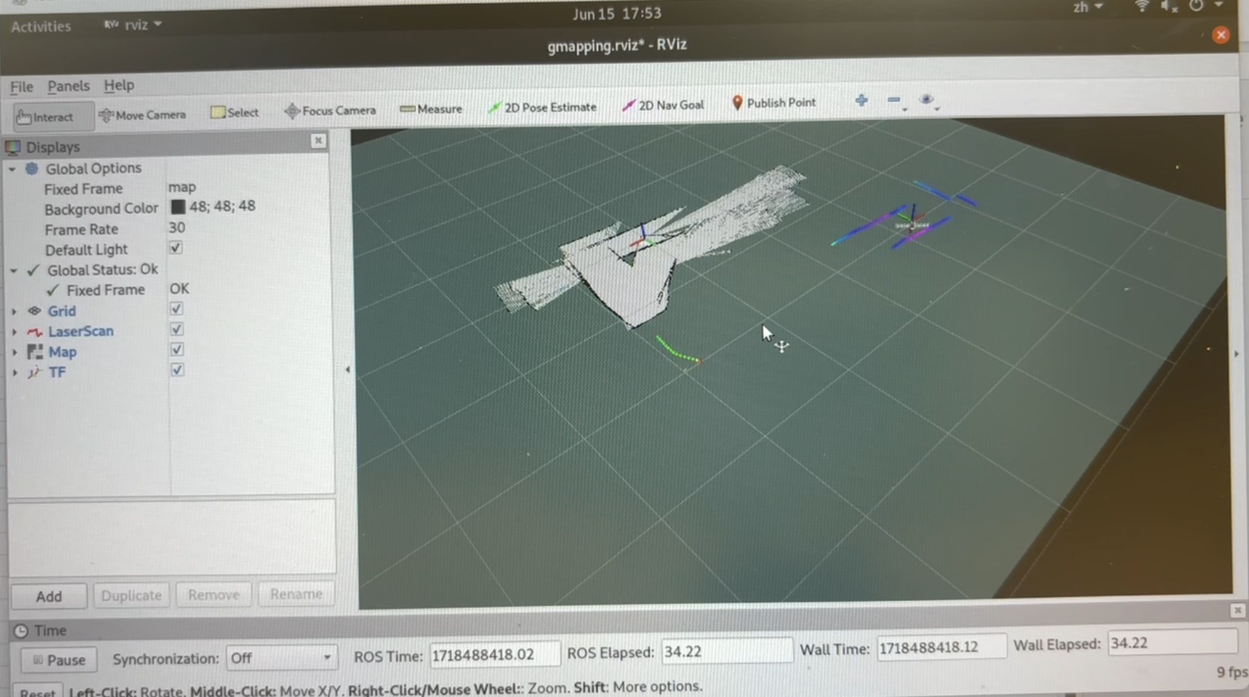
Figure 23: the mapping result of my apartment.
Figure 24: mapping my apartment
Figure 25: Increase the tf broadcast frequency, increase the map update frequency. The result is a bit better
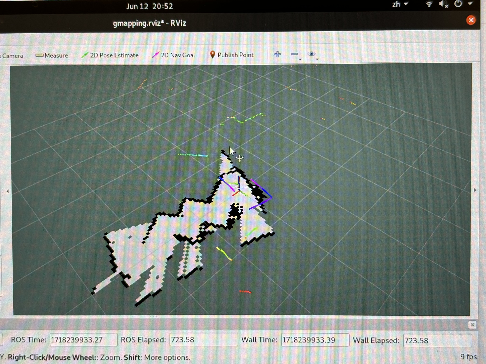
Figure 26: it looks like gmapping doesn’t trust the odometry because it sometimes change the correct position to the wrong position.

VI. SLAM and the Racing Track

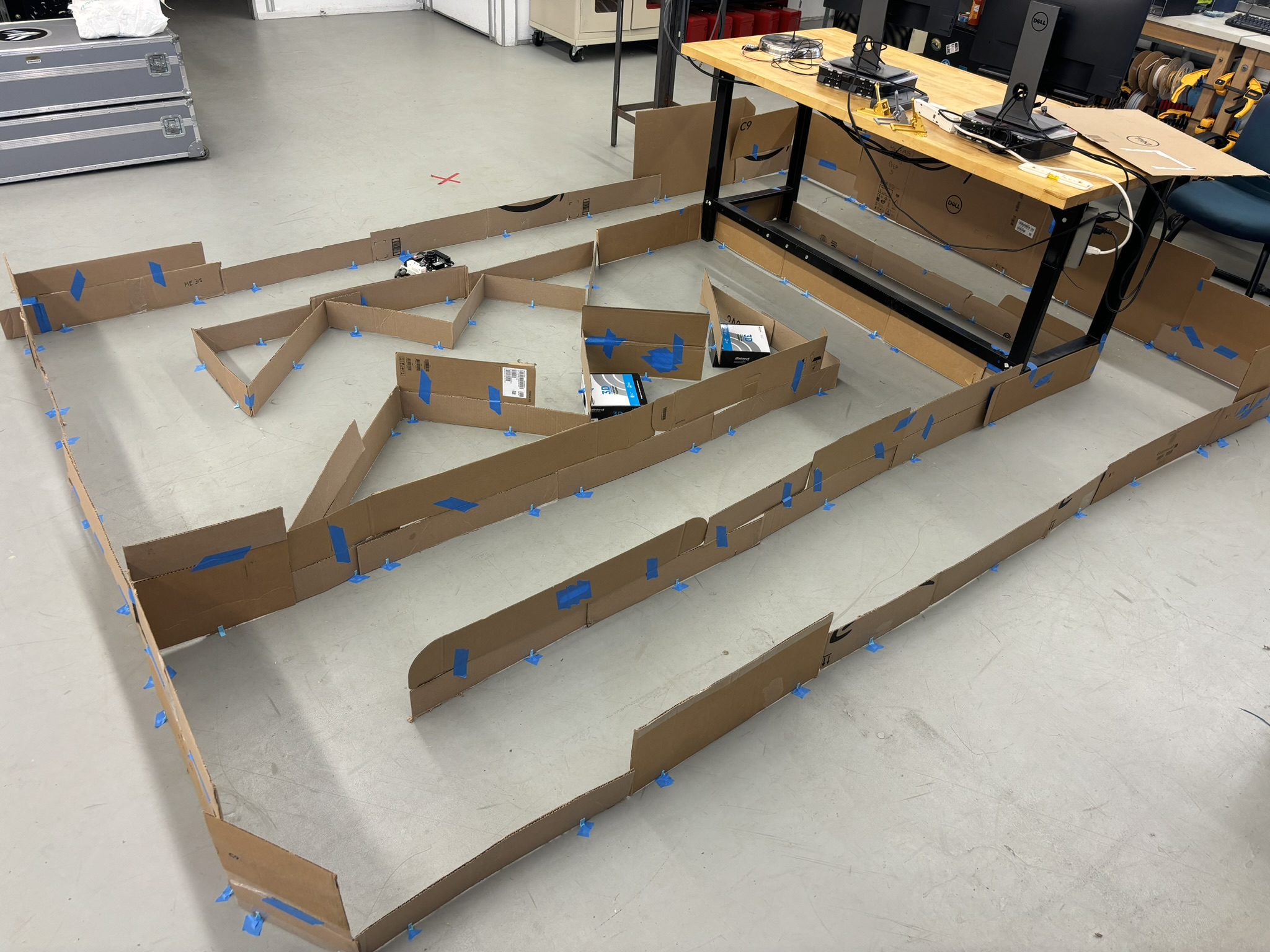
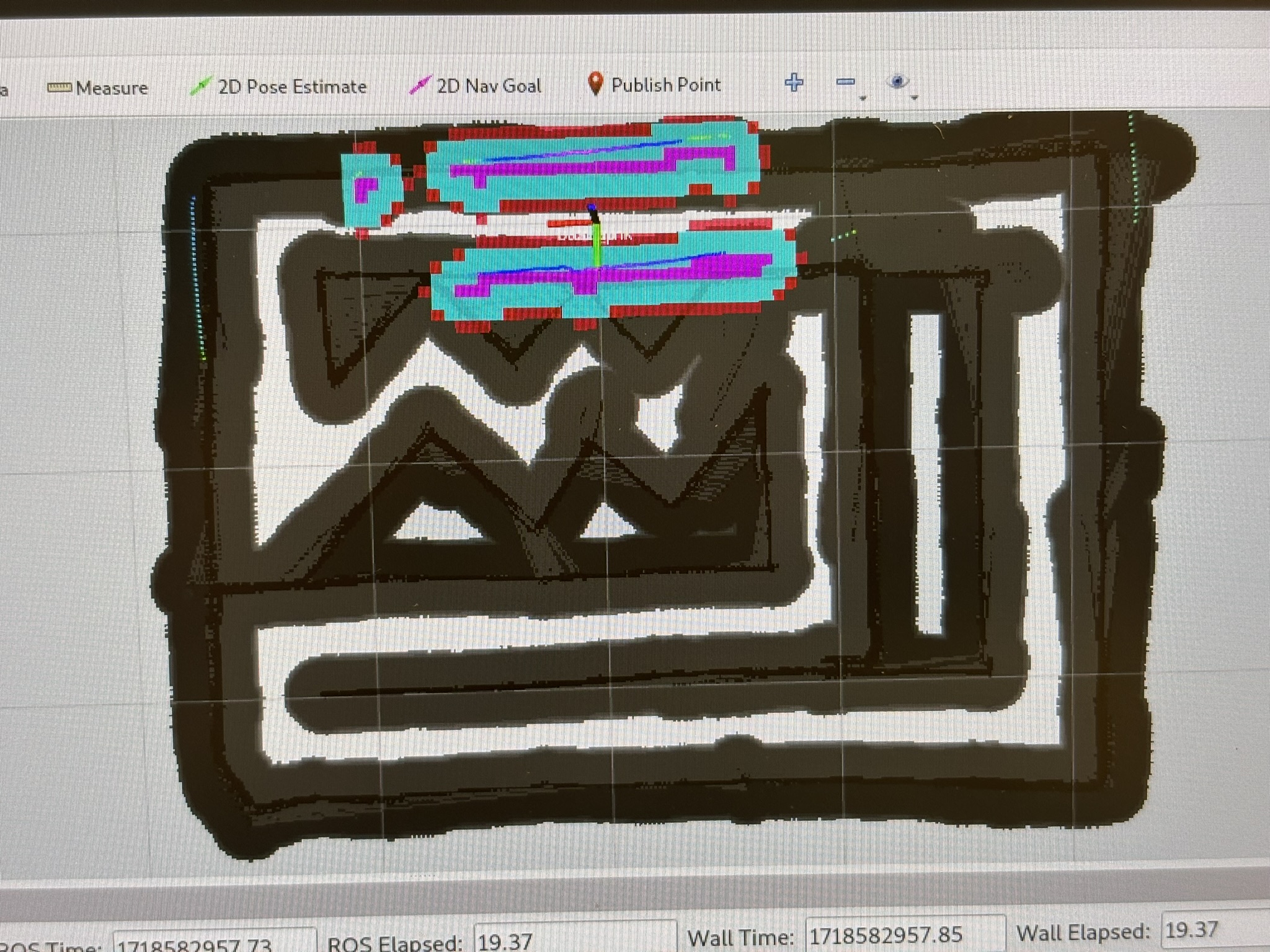
I built the same racing track as I raced in ME444.
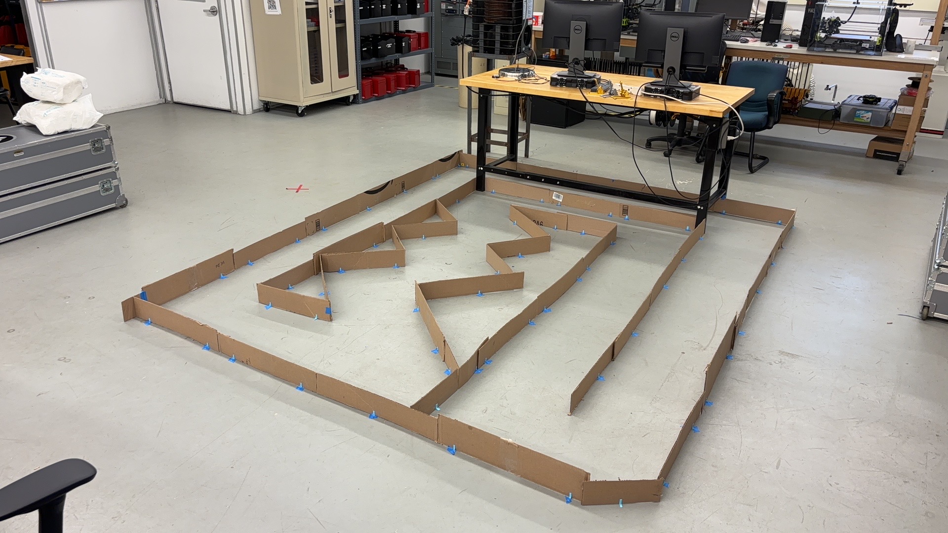
Figure 27: the racing track
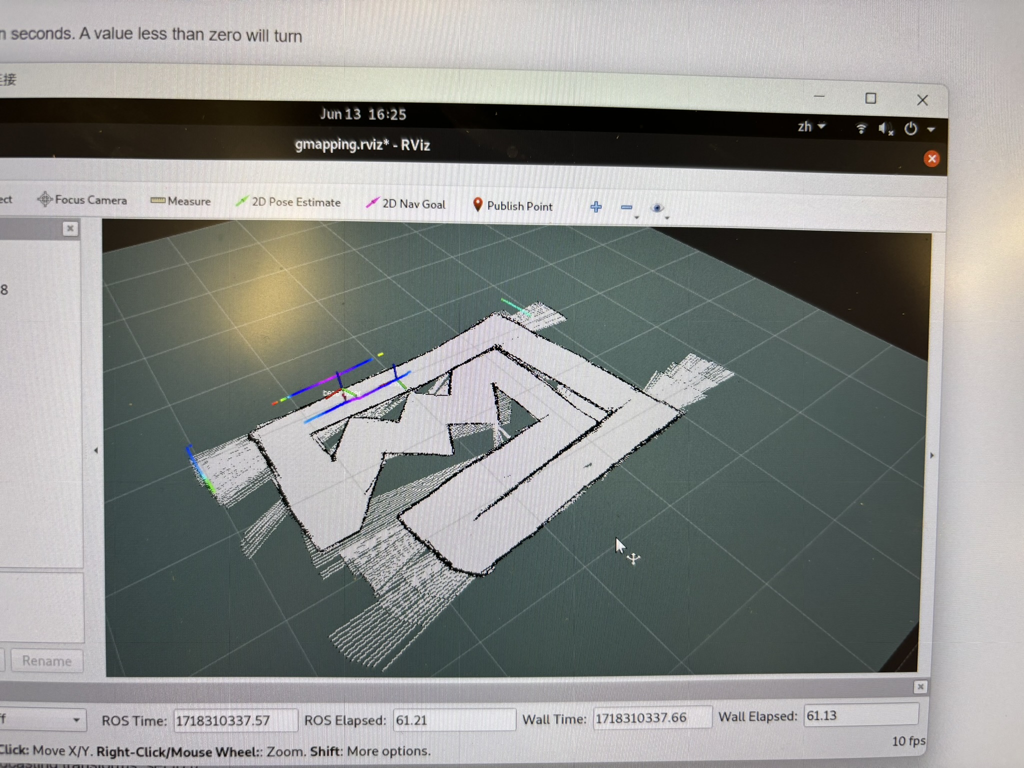
Figure 28: first run on the track
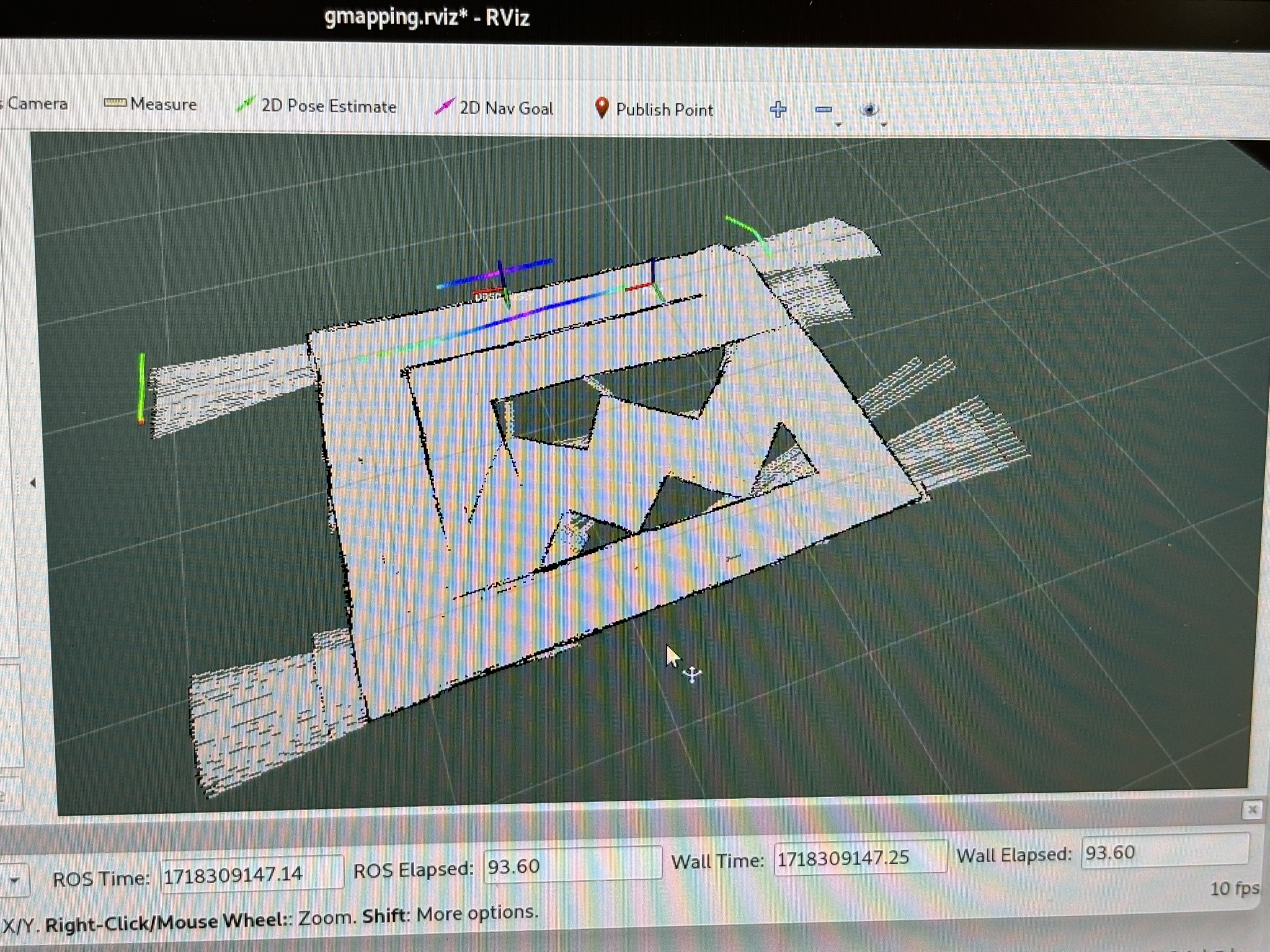
Figure 29: but the slam result is nothing, and I noticed that the LiDAR is not emitting horizontal laser rays. When the bot is far from the wall, the laser can travel over the wall, and detect futher objects
Figure 30: I am trying to fix the non-horizontal problem, but that’s not something I can do. Furthermore, even it’s horizontal in CAD, the nose still tilts up due to the rear wheel deformation.

Gmapping doesn’t trust the odometry. This causes the map can’t be generated correctly.
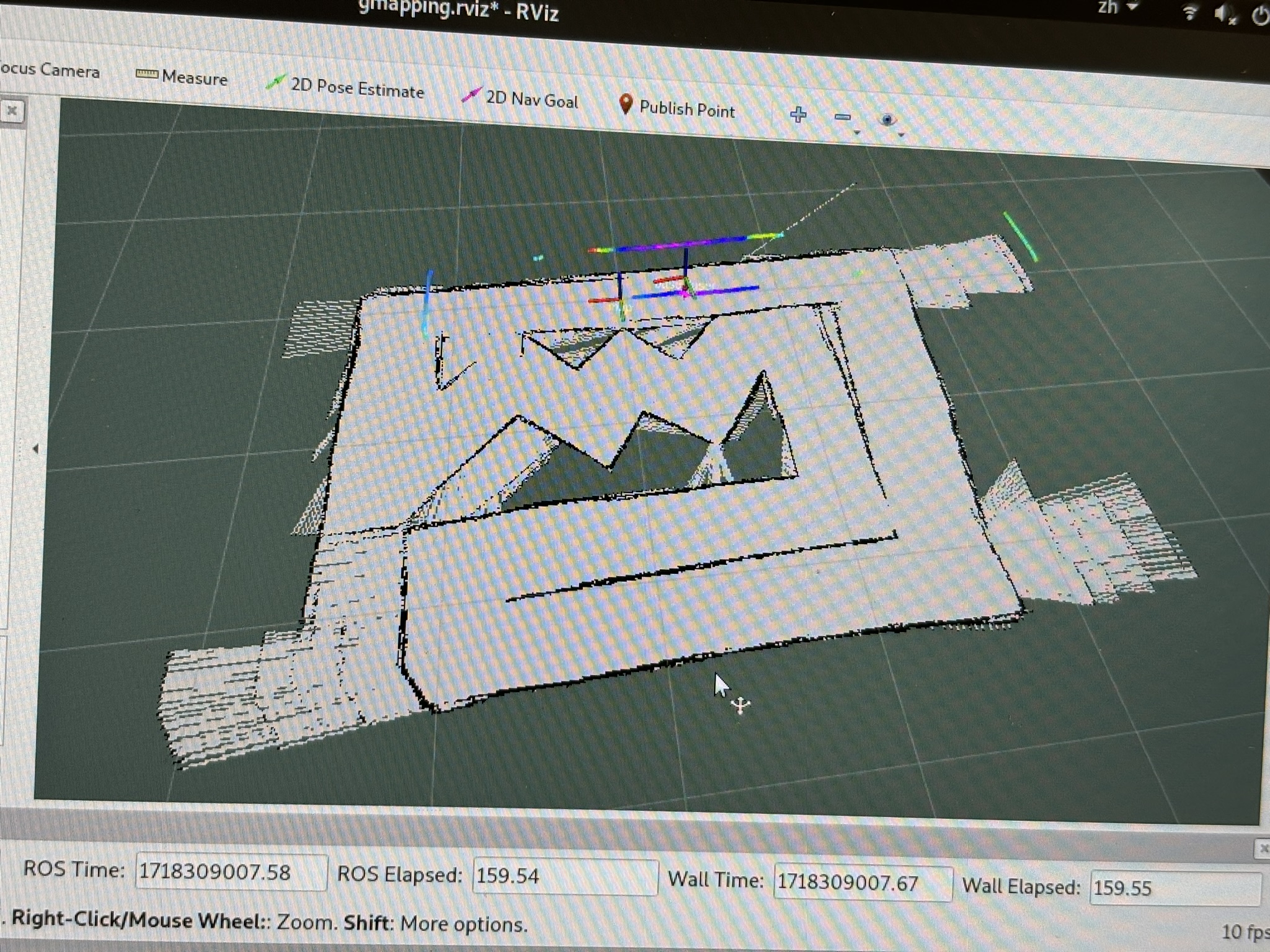
Figure 31: so I increased the wall height, adjust the track, and the same problem appears.
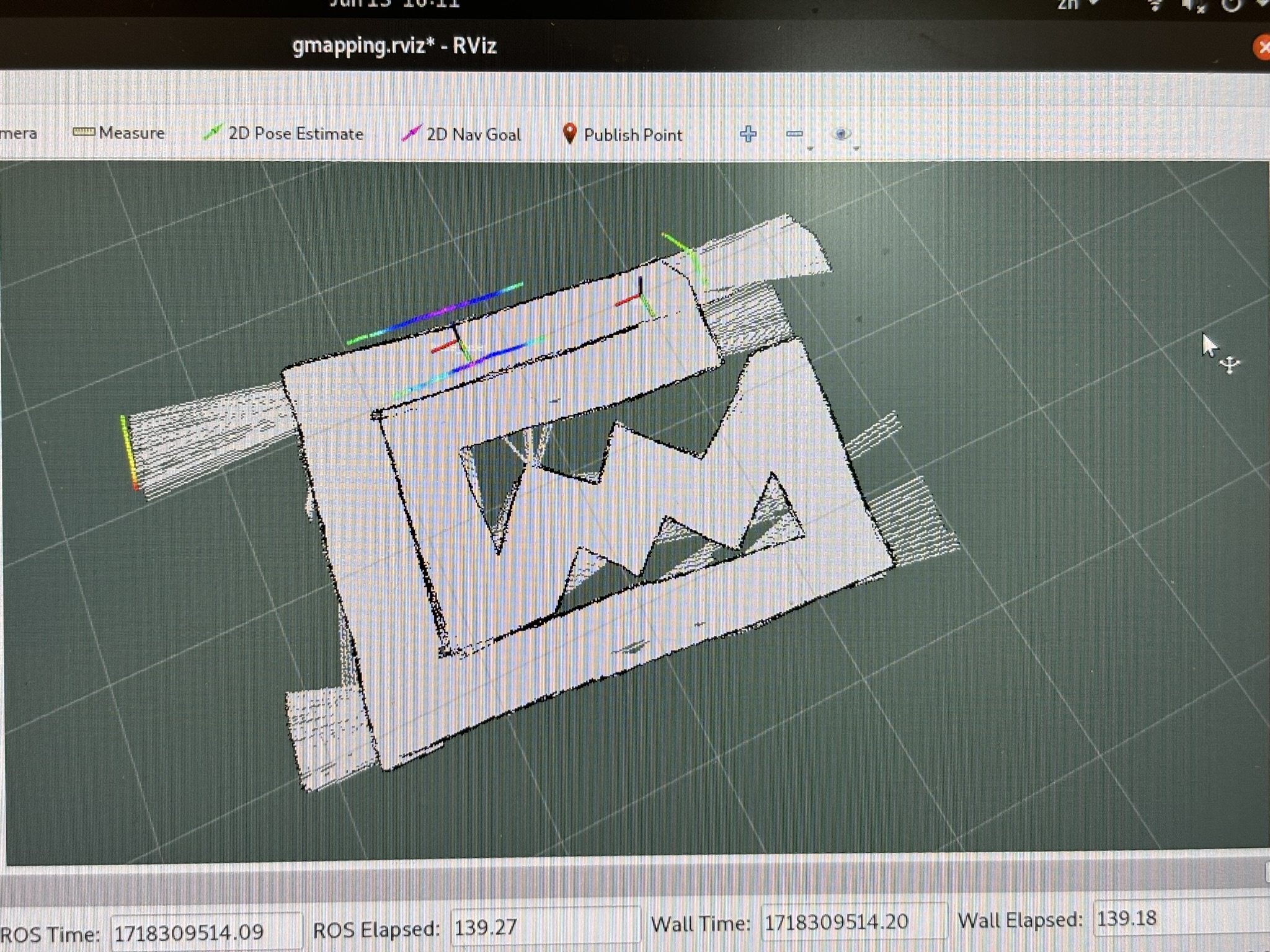
Figure 32: the section on the left always got merged
Figure 33: gmapping never trusts odometry. The map was correct, but it will change it in the next second.
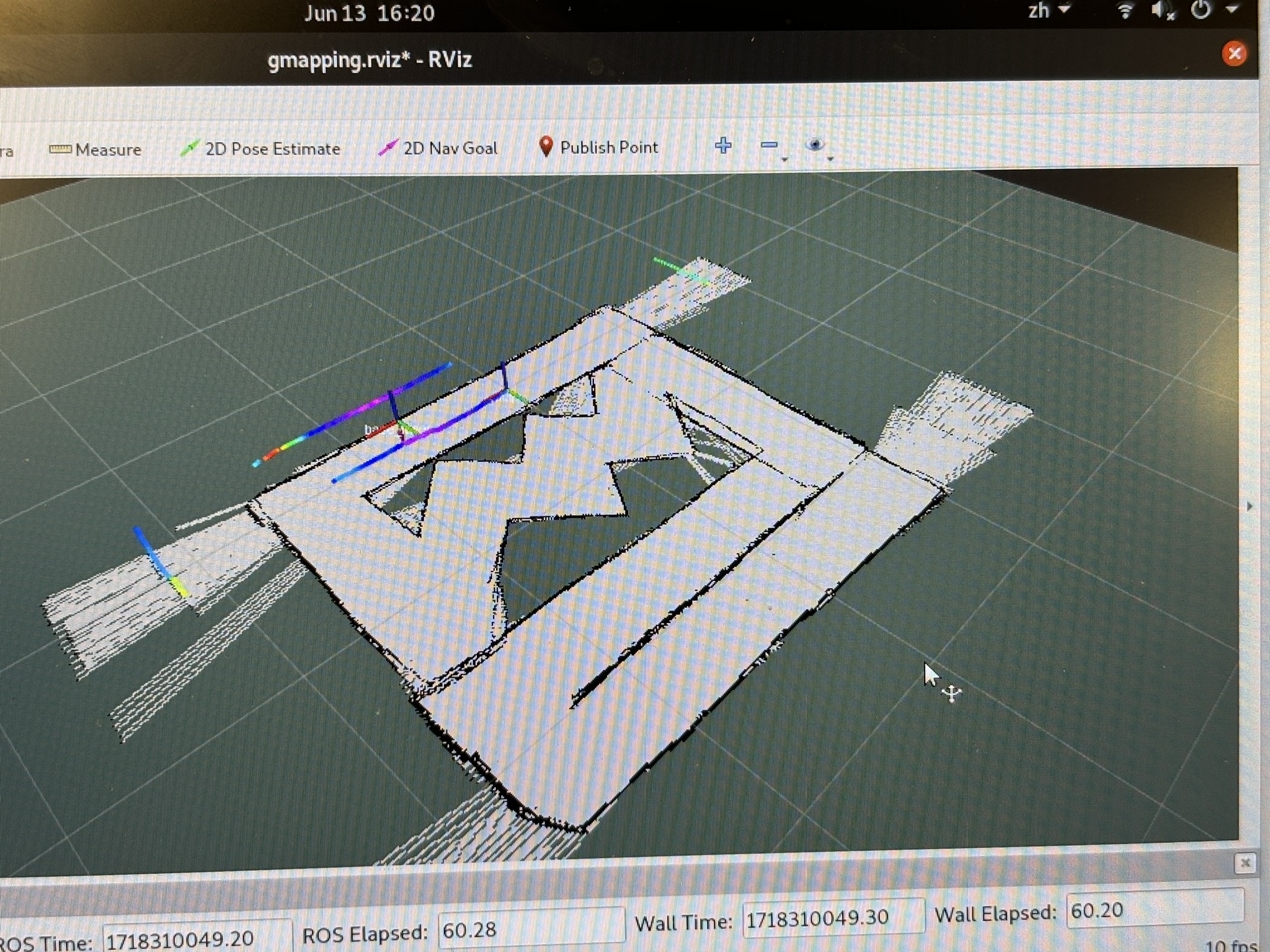
Figure 34: the two scan section on the upper right corner were correct, but gmapping is too SELFISH!
Figure 35: I really have nothing else to say.
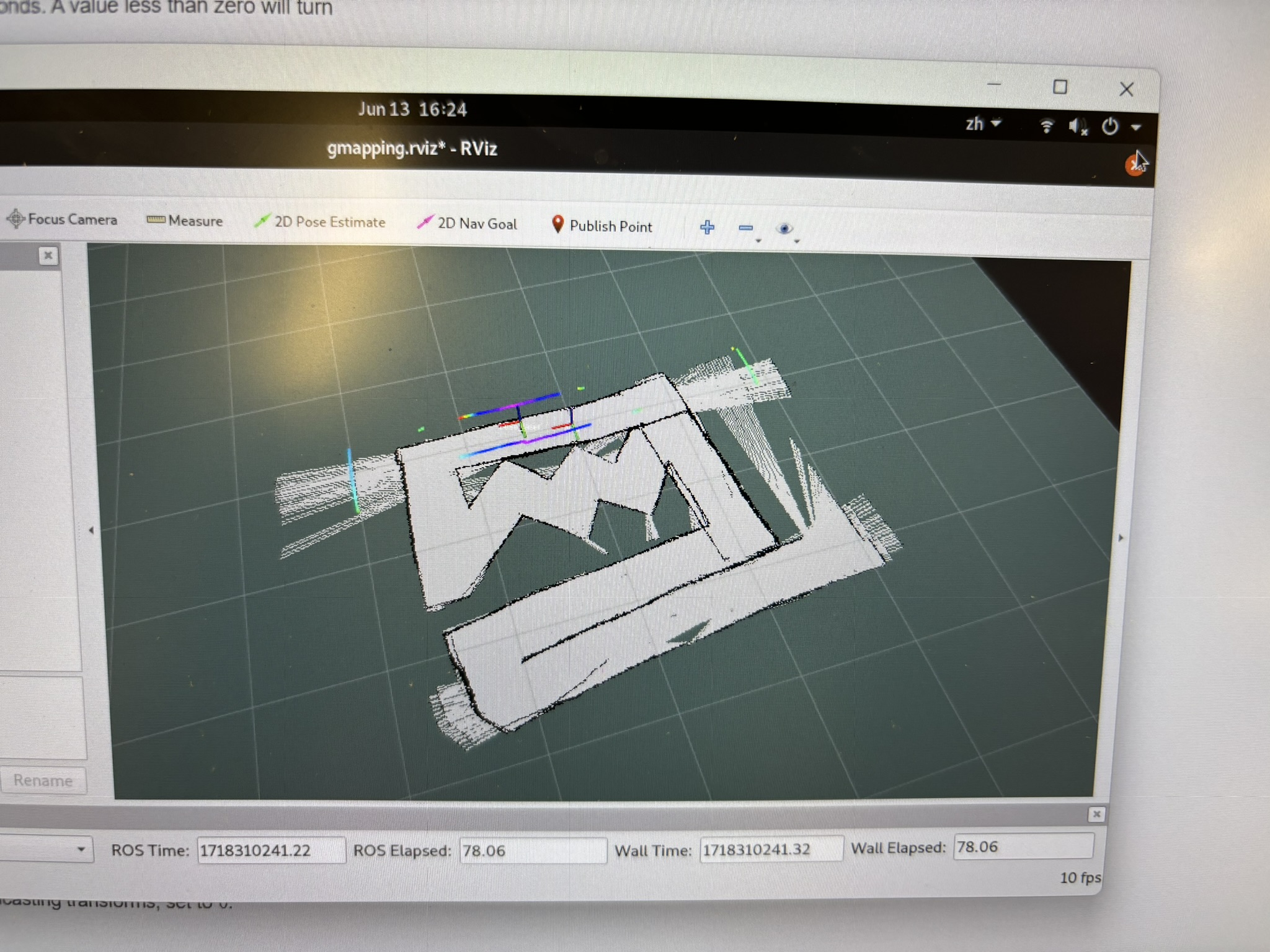
Figure 36: this one is even worse
Figure 37: the track after I increased the wall height
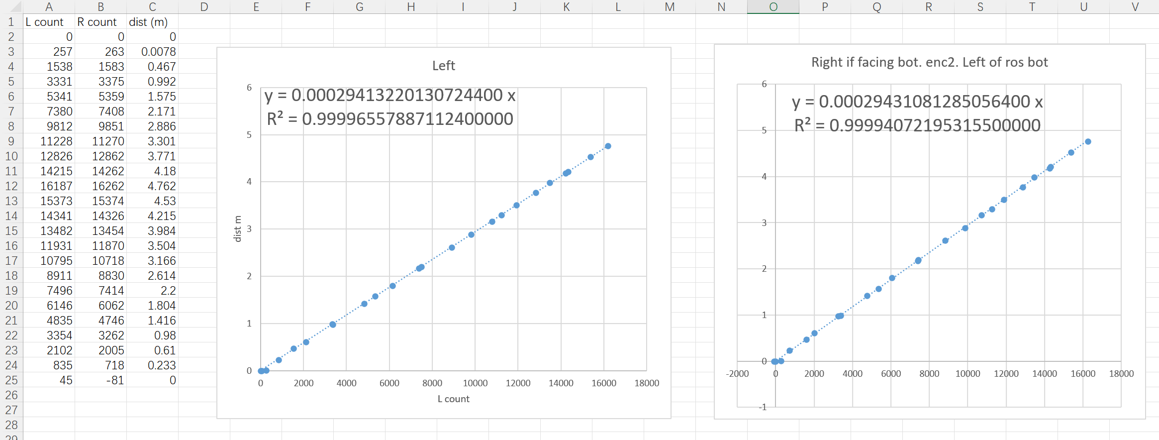
Figure 38: so I calibrate the odometry again, with left and right encoder separately.
Figure 39: start from 0m
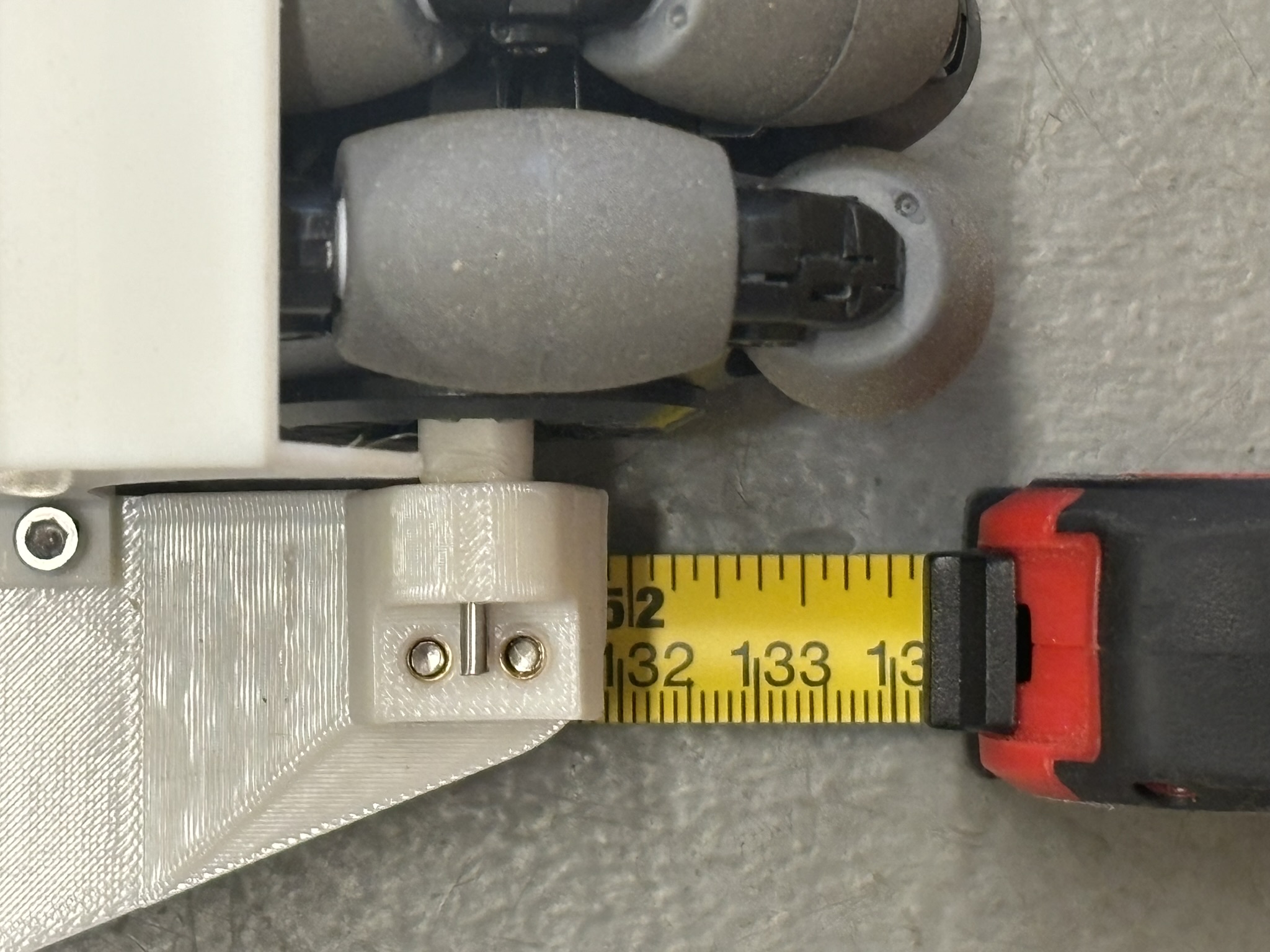
Figure 40: and let it run about 1.32 m
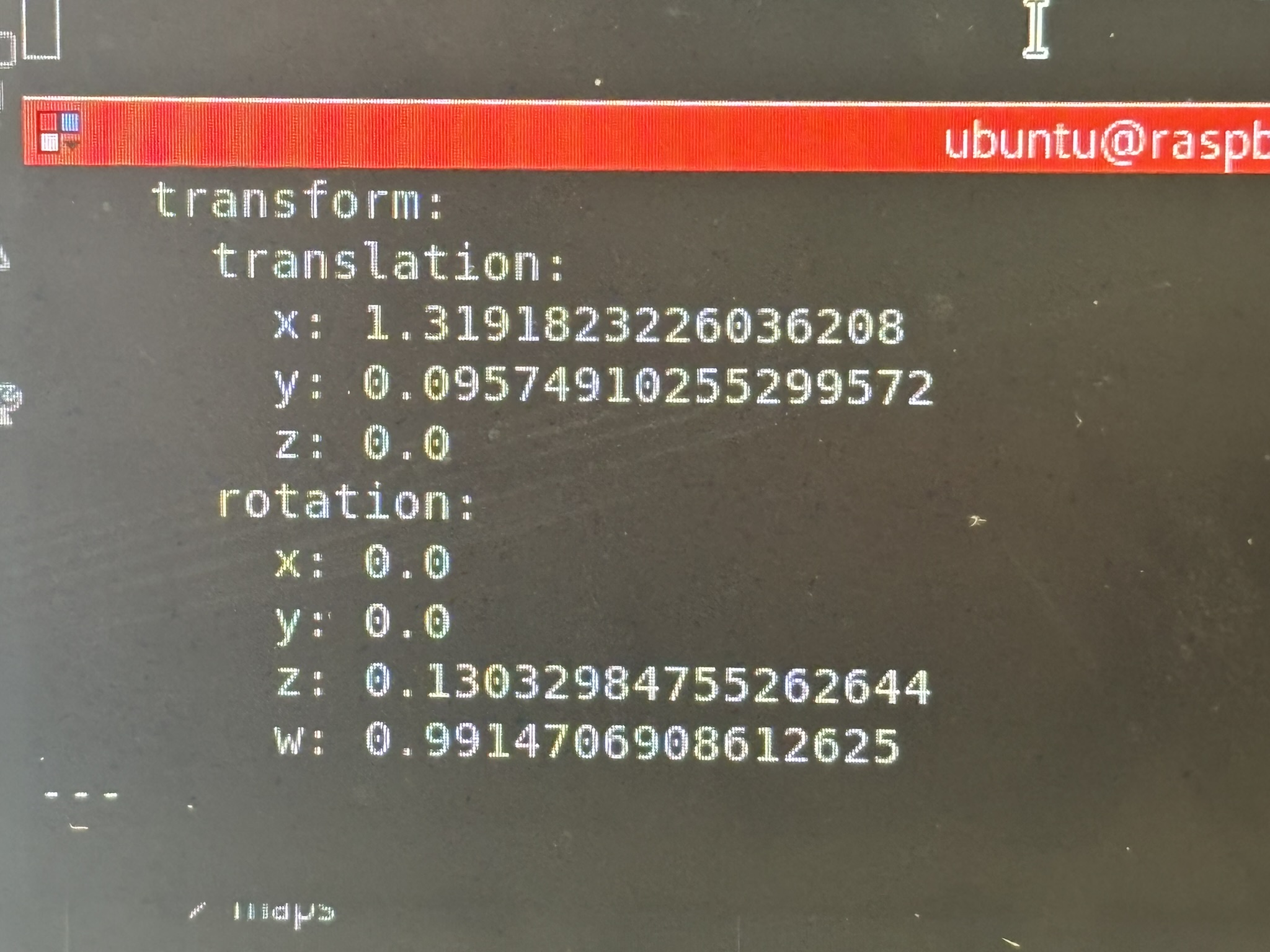
Figure 41: the x component of the tf is really precise, 1.319m.
Figure 42: but the problem still exist. At 00:37, you can see the position of the bot was shifted. IT WAS CORRECT!
Figure 43: ang gmapping just refuse to work!
Figure 44: so I test the odometry precision, it’s pretty good.
Figure 45: then I tried to let it run a very short distance, and wait a few seconds. Finally the stupid gmapping can calculate it. And even this video was the last one after gmapping failed to map 6 or 7 times!
Figure 46: this mapping took me 6 days!

VII. Navigation

Figure 47: after the mapping was done, I started to work on navigation.
Figure 48: even the gyro is always drifting, but amcl should update the position at the thresholds. Even the thresholds were set to 0.05 radians and 0.1 m, amcl just refused to work!
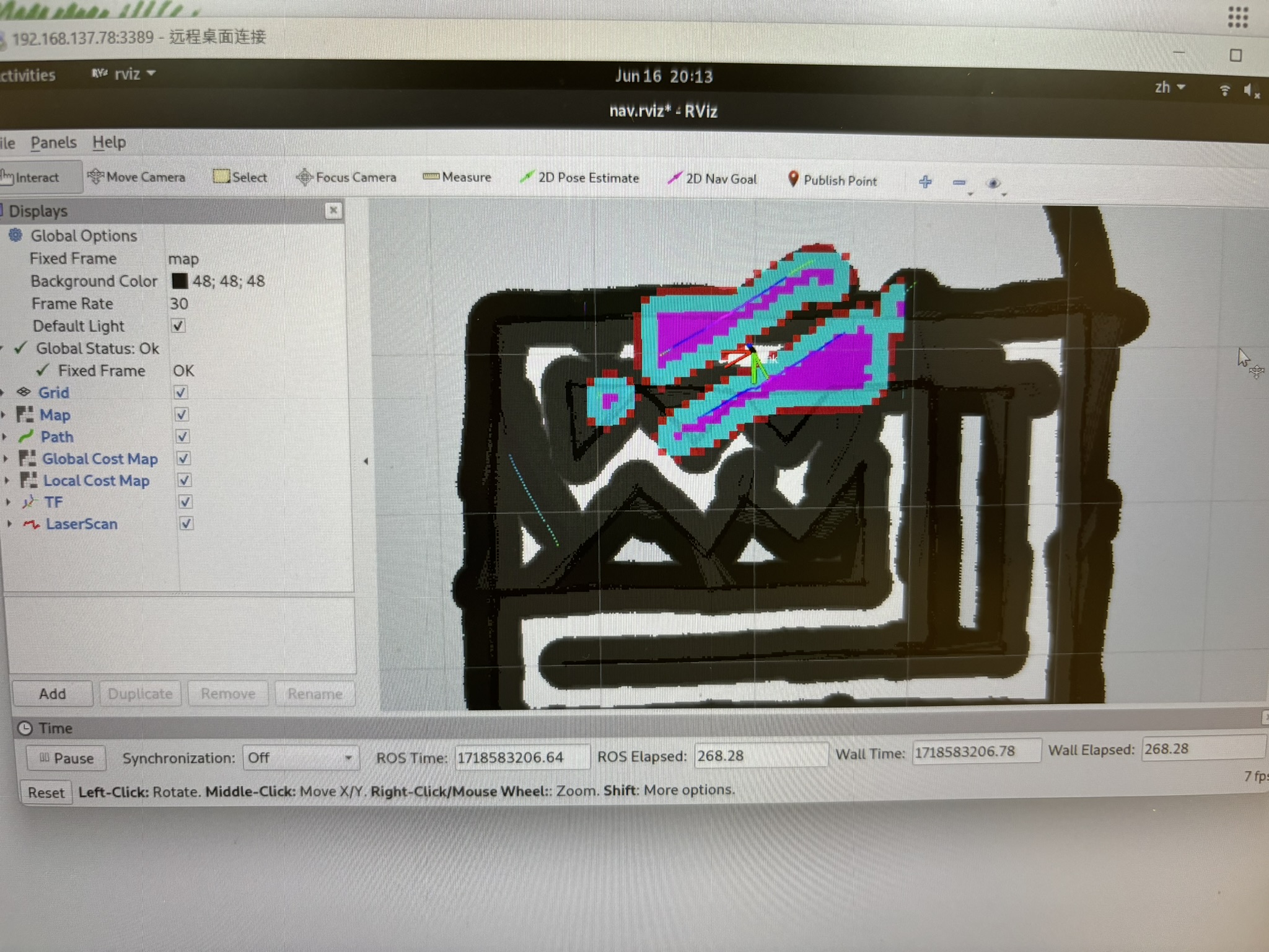
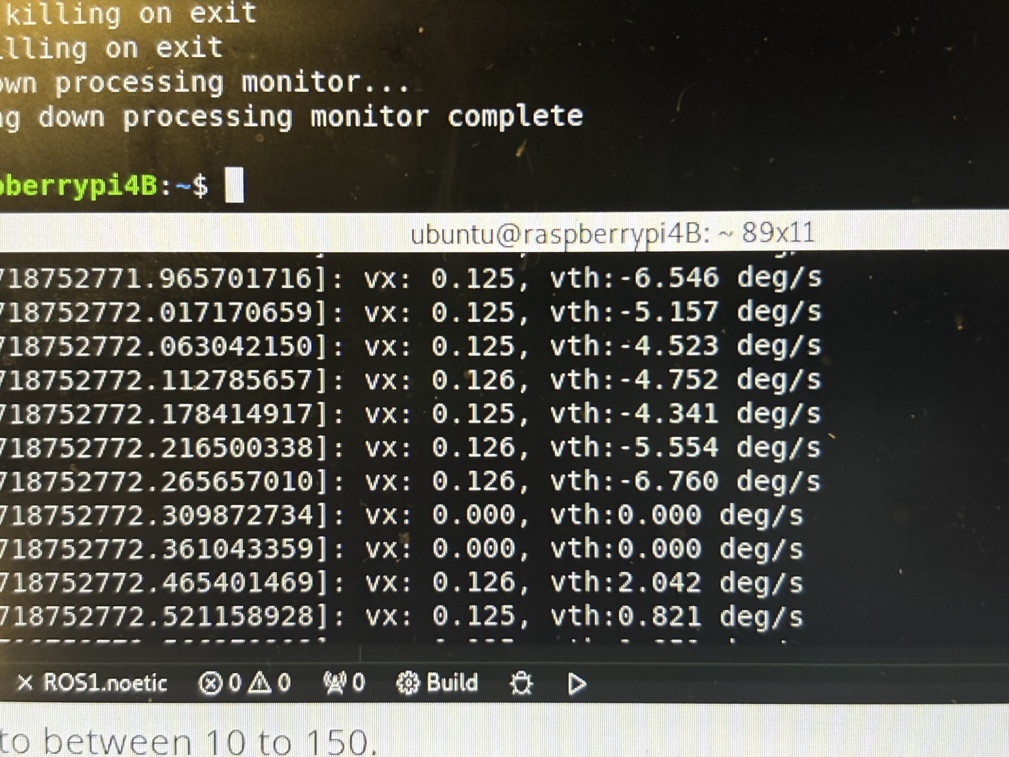
Figure 49: so I mapped part of the first floor of NISW near the restroom, and hopefully larger room can make it easier. But DWA planner is trash! The max speed was set to 0.125 m/s even I change the config file. It was able to run at first, and then the speed become 0!
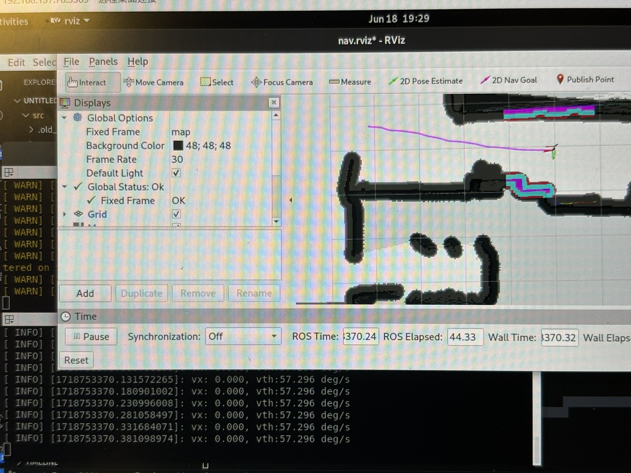
Figure 50: the path was generated, but the output speed is 0!
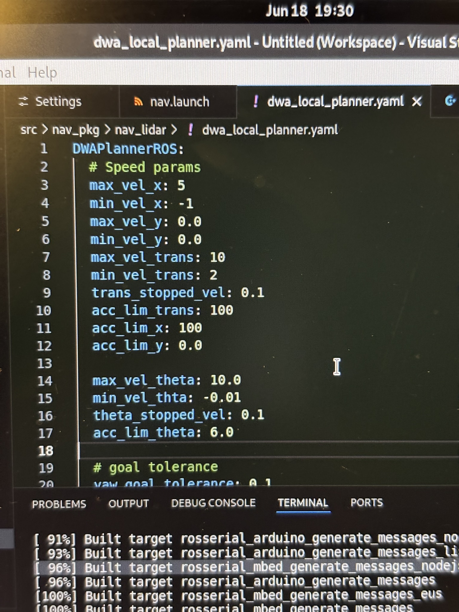
Figure 51: the max speeds were set to very large already.

I had to increase the inflation radius and the robot radius by a lot, so DWA wouldn’t smash the bot into the wall. DWA had zero successful runs.
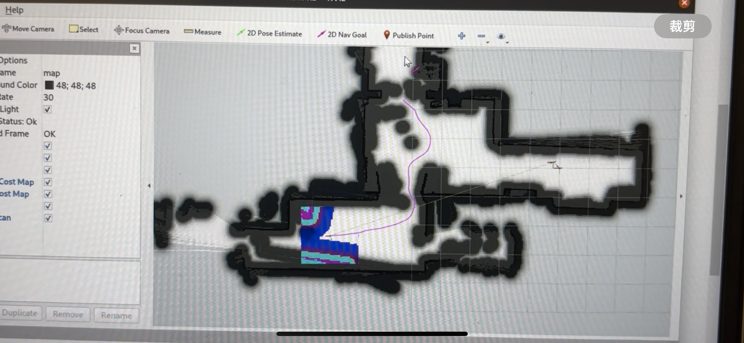
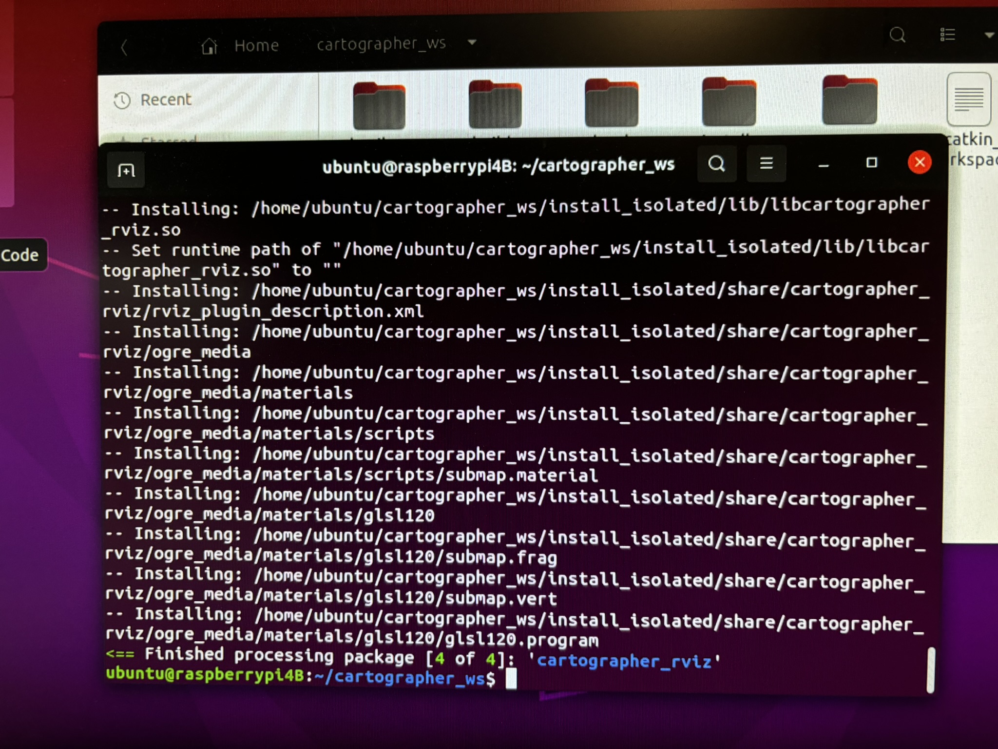
Figure 52: since DWA refused to work no matter how, I switched it to TEB planner, it worked for the first a few times.
Figure 53: but it never updates the temporary obsticles, so it can navigate to the next point continuously
Figure 54: and then TEB refused to work! the path was generated, but it’s not going anywhere!
Figure 55: the bot reached the destination, but the amcl never provides the correct position!
Figure 56: if I give it an estimated position, and move it around, amcl can provide kind of accurate position (the red arrows are concentrated)
Figure 57: it’s such a pain to use amcl. I have nothing else to say.
Figure 58: tired
Figure 59: path is there, just go. Why are you not going!
Figure 60: two days later (07/11), this was the best one so far. All of the other tests failed. The bot went off the course in any direction you could imagine. It’s just ridiculous.
Figure 61: so I tried to use the pure localization of Cartographer, but it took me ******* 39 HOURS TO INSTALL! I tried more than 10 toturials, and none of them worked! Also, pi4B kept freezing when it’s compiling it!
Figure 62: and it took me another hour to configure the Cartographer. The next day (07/15) , SLAM worked as expected.
Figure 63: another 7 days later (07/22), finally the navigation worked with AMCL. Endless tests were conducted, it’s just pain. Finally the bot could do multi-point navigation, and it took me more than a month to make it move from the first point to the second point.
Figure 64: but the output of the speed commands were not right when using pure localization of the Cartographer. So what’s the point of the existence of Cartographer? What’s the point of wasting my time?

VIII. Conclusion

This project deepened my impression of open source: using open source is just a pain. The code keeps failing, and I guarantee that more than half of the code is error-reporting related. If their code really works well, they wouldn’t put that many error messages in there. Tutorials are outdated, key questions were never answered, and the developers only responded “here is the doc go read by yourself” and closed the post. I’m so sure that the Cartographer developers couldn’t install Cartographer successfully on the first try.

Using open source will generate endless problems by iteration. What does it mean? See code below:

void try_to_solve_the_problem( problem ){ // void, because it never returns
  if (find_a_solution(problem)){
    new_problem=generate_a_new_problem();
    try_to_solve_the_problem(new_problem);
  }
}

I don’t know if it’s the hardware problem or software problem, it’s very lag when running on a 4GB RAM pi4B. I really suspect that ROS was not designed on this board. Raspberry pi 4B only has a 4 core CPU with the clock speed of only 600MHz, same as Teensy 4.0 while not overclocking. It’s too slow.

Pain.

Leave a Reply

Your email address will not be published. Required fields are marked *