I. Intro
Date: June 23, 2023 – June 29, 2024
I finished the ME375 Control II course during the spring of 2023, and I have a better understanding in PID which confused me and attracted me for many years. I don’t remember exactly why I started this project, but that night, I just finished the research of the step motor with Arduino and really wanted to build a flight controller. So I bought the GY-87 circuit board, which has a built-in gyroscope, accelerometer, barometer, and magnetometer.
Part 1 covers what I did from June 2023 to July 2023. Due to the time limit, I had to pause the project.
Part 2 covers what I did from Aprial 2024 to June 2024.
Reference:
little-scale: Teensy Basics 5: Port Manipulation
Part 1. Intro to the world of unknown
At the beginning of this project, I started with the 3-axis accelerometer and 3-axis gyroscopes. Then I realized the movement of the drone could affect the accelerometer reading, so I spent another week learning the Kalman filter and derived the code for roll-pitch reading and height reading on my own. After I solved the pitch and roll, I was trying to solve the height and yaw, but I wasted too much time on there. First, the tilt compensation of the magnetometer never worked after I tried and modified the signs and the formula many times. An inertia angular speed in the z-direction is enough to lock the heading. The BMP180 pressure sensor and the altitude sensor took too long to read. The control loop was 4 ms, but getting the reading from BMP180 required 22 ms (this was what I found out in September 2023). During the summer, I was still unaware of the super slow reading speed. At the end of the summer, I was still using analogWrite() function, a control loop of 28 ms on a Mega 2650, an imperfect Kalman filter, an imperfect PID controller, and other bugs in the code. As a result, it didn’t fly.
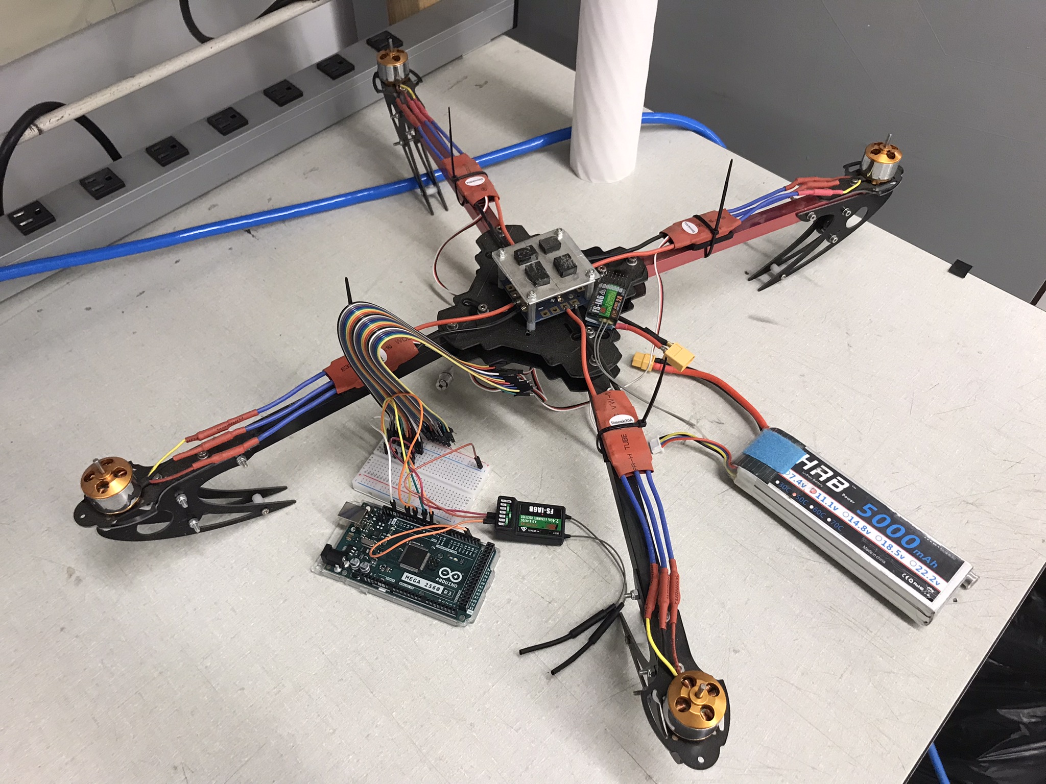
While waiting for the chip to arrive (bought on 06/23), I started constructing the code and testing the hardware. I learned cascade PID control, Kalman Filter, tilt compensation, and many other theories and algorithms. These took me a month, and when I gave up the magnetometer and tilt compensation, it’s already near the end of the July.
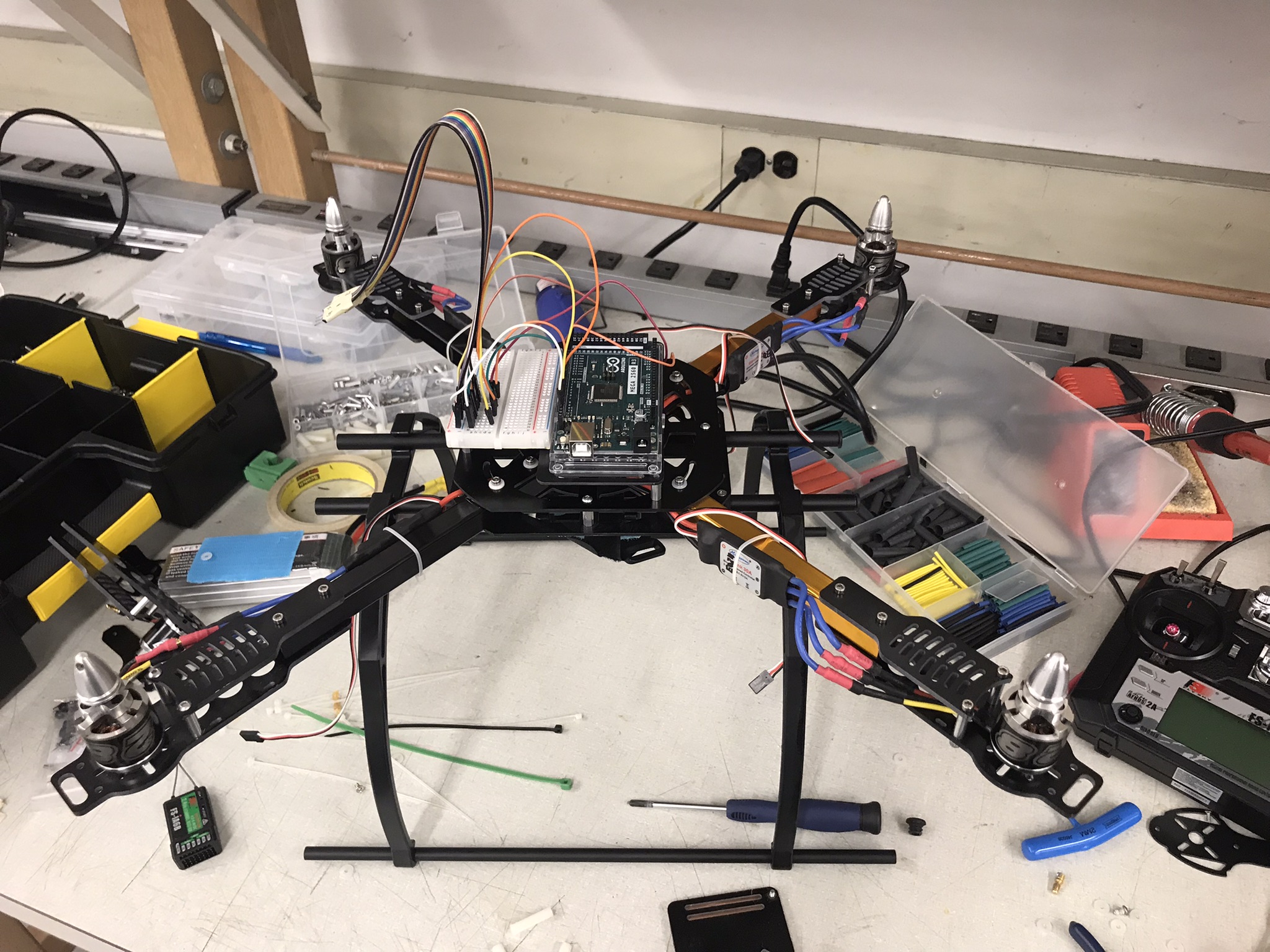
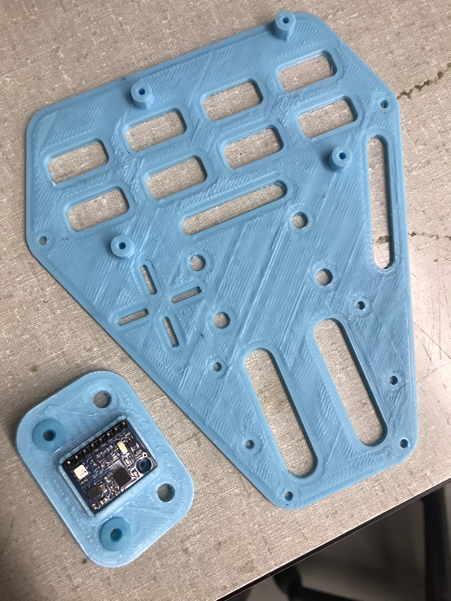
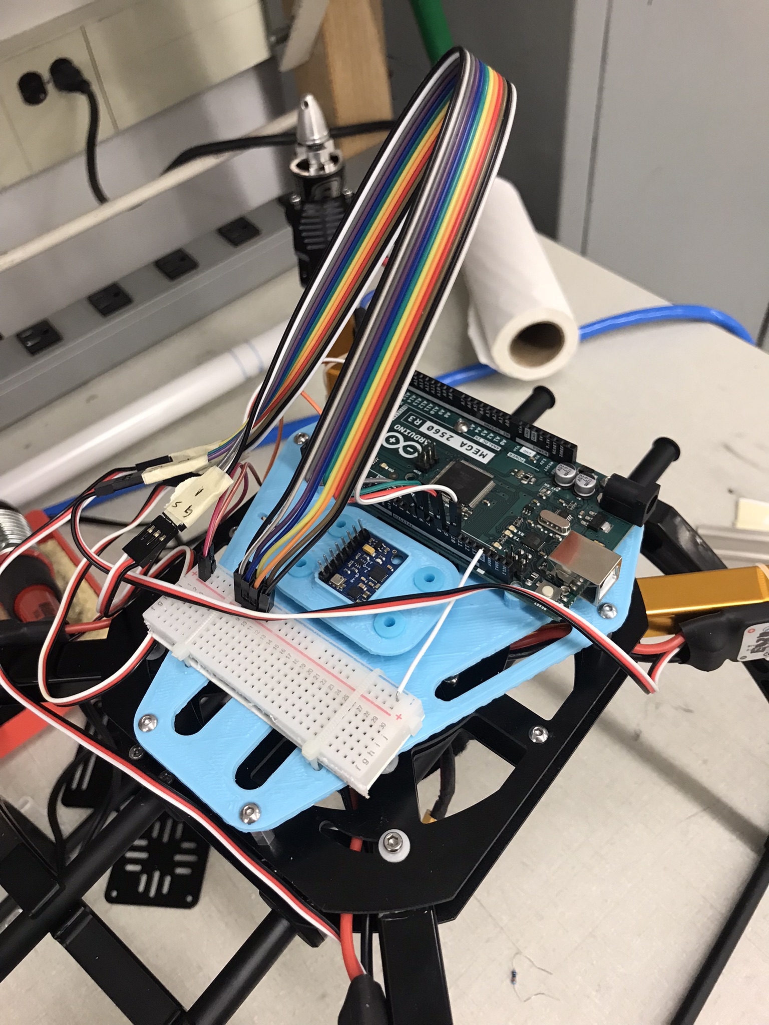
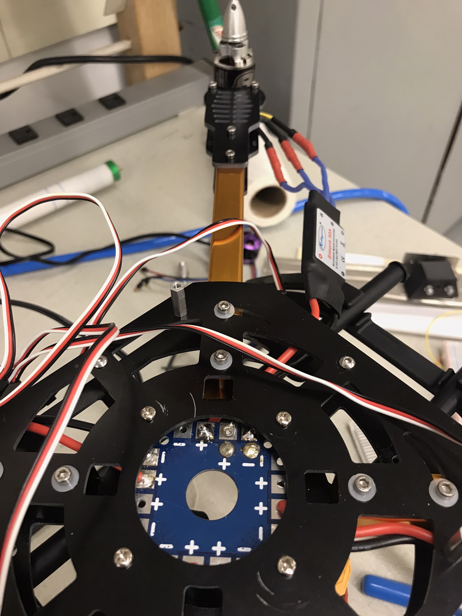
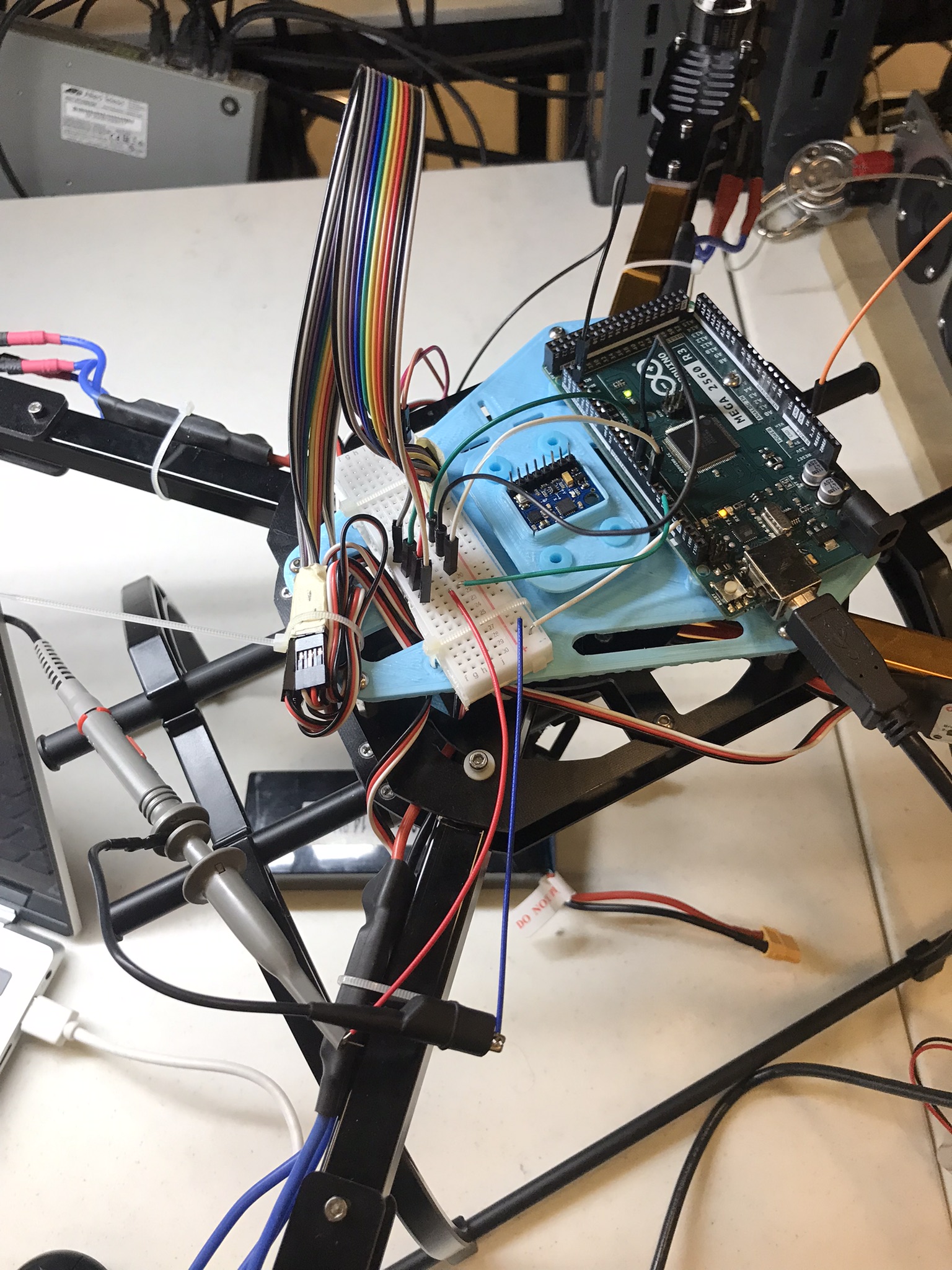
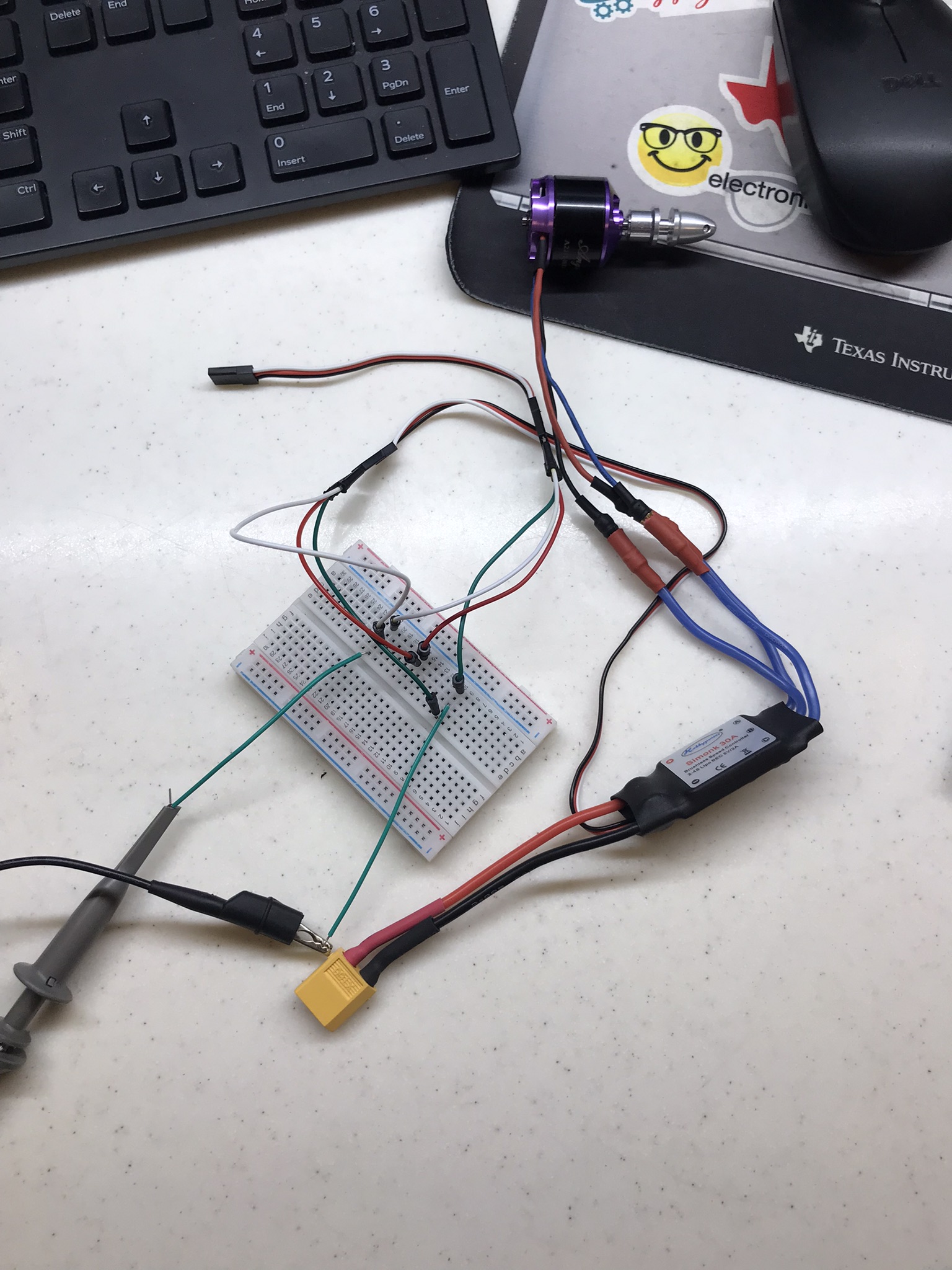
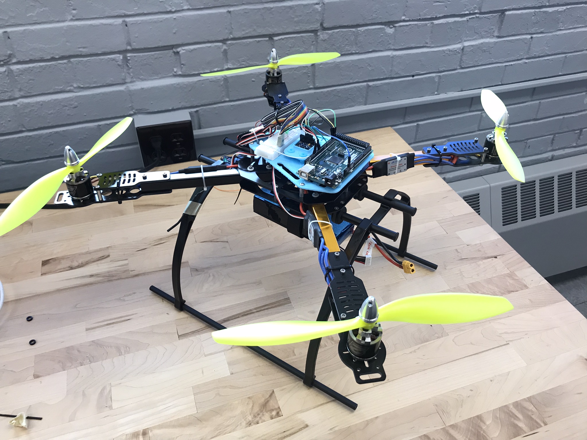
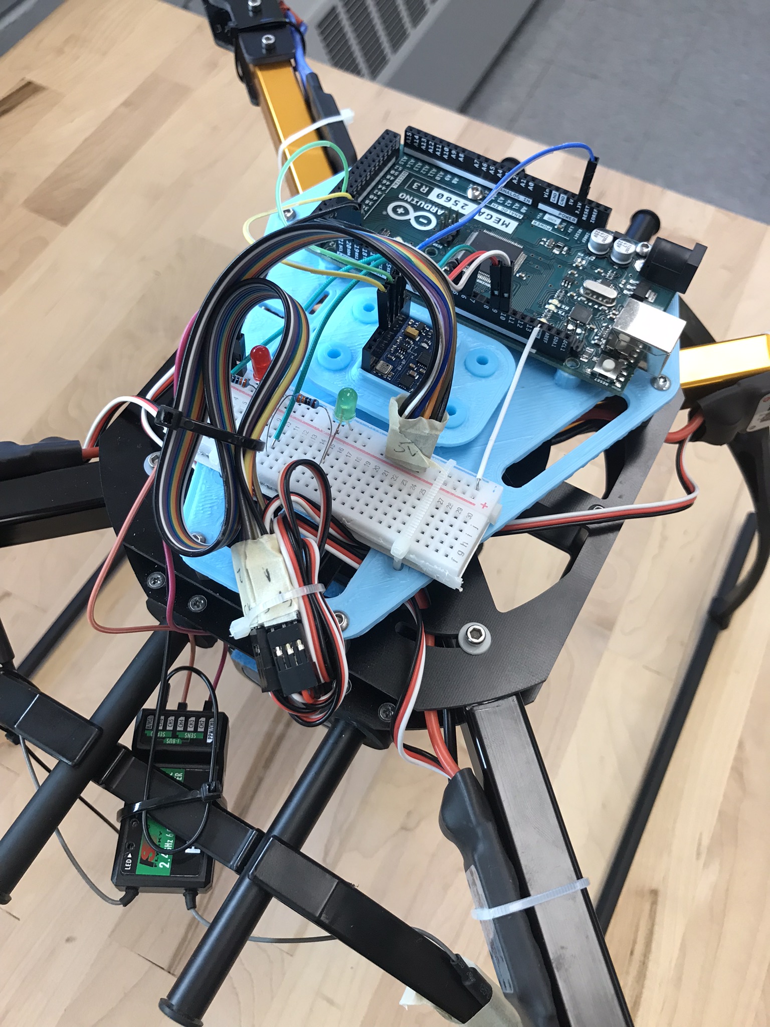
Of course, it’s not going to fly.
Part 2. The success.
At the end of July, I had the last test. After that, I start working on this website. Then, I started the busiest semester because I had FIVE LABS! They are Fluid Dynamics(ME30801), Toy Design (ME444), Heat and Mass Transfer (ME315), drones (AT409), and composite (AT272). In February, I was working on the battle bot. During the winter break, I was working on the Ferris wheel till April. That’s why I resumed working on this project in April.
| Issue | Before | After |
| Control loop too slow (28ms) | Mega 16MHz+BMP180 | Teensy 4.0 600MHz, only MPU6050 |
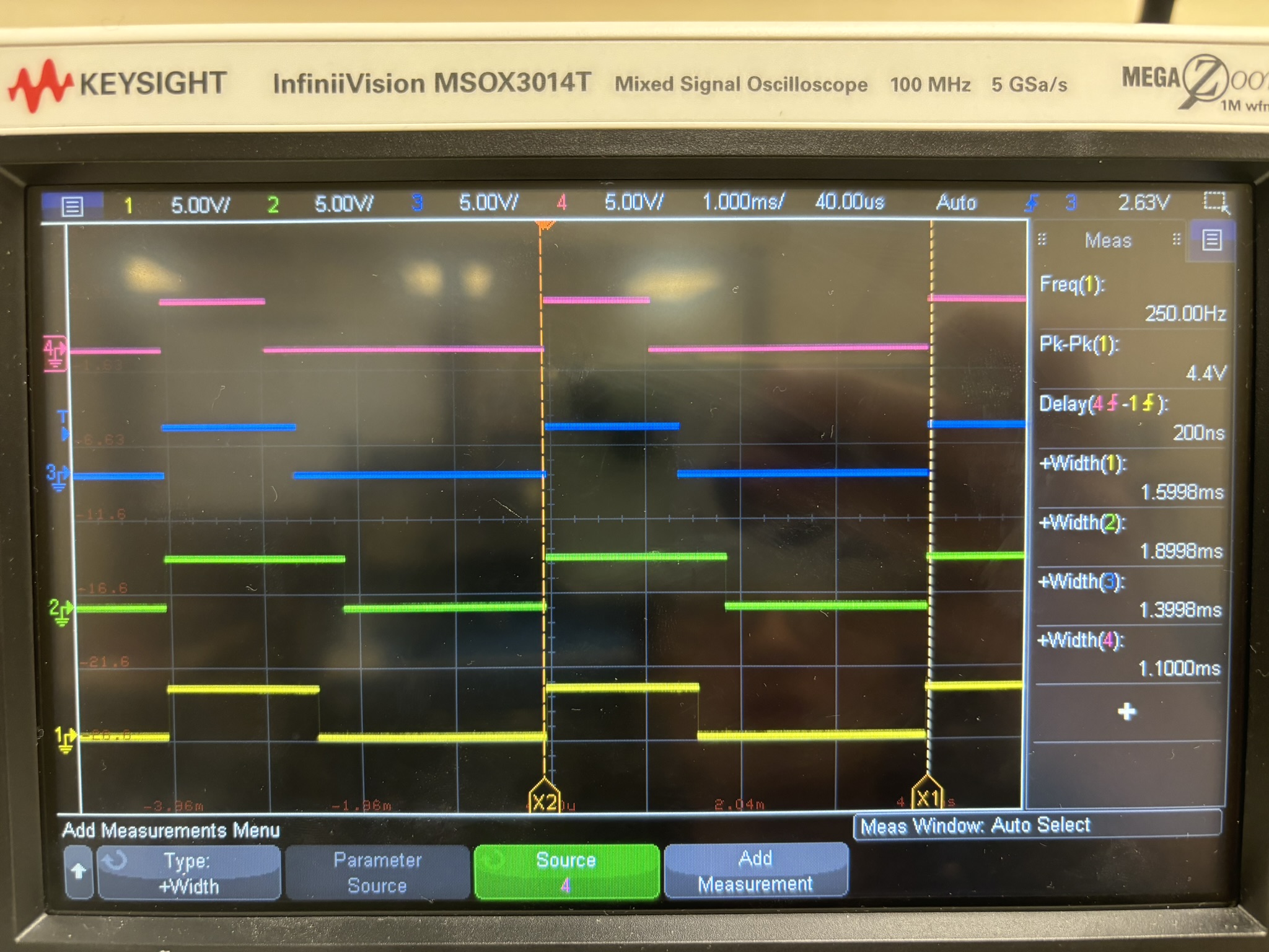
| Motor output not precise | Used analogWrite to match the 0 to max speed of the ESC. Use writemicroseconds() function of the servo library. | Learned bitwise OR and AND assignment operator. Used Teensy port manipulation. Used digitalWriteFast and timed loop to output PWM signal that worked with ESC. Looks like the signal period doesn’t matter, fixed period and 1000 to 2000 us HIGH signal matter. |
| When pitch or roll just starts moving, roll or pitch reading also moves | Used the kalman filter derived on my own | Used the Kalman filter derived on my own |
| Input reading won’t change if the transmitter lost link | Can’t figure out a way to get new readings. | Input reading won’t change if the transmitter link |
| PID controller | angle error change=current error-previous error | angle err change=angular speed for the timed discrete loop. |
| Fixed the bugs | ||
| FC mount | non removable | removable, so I could take it home and continue working. |
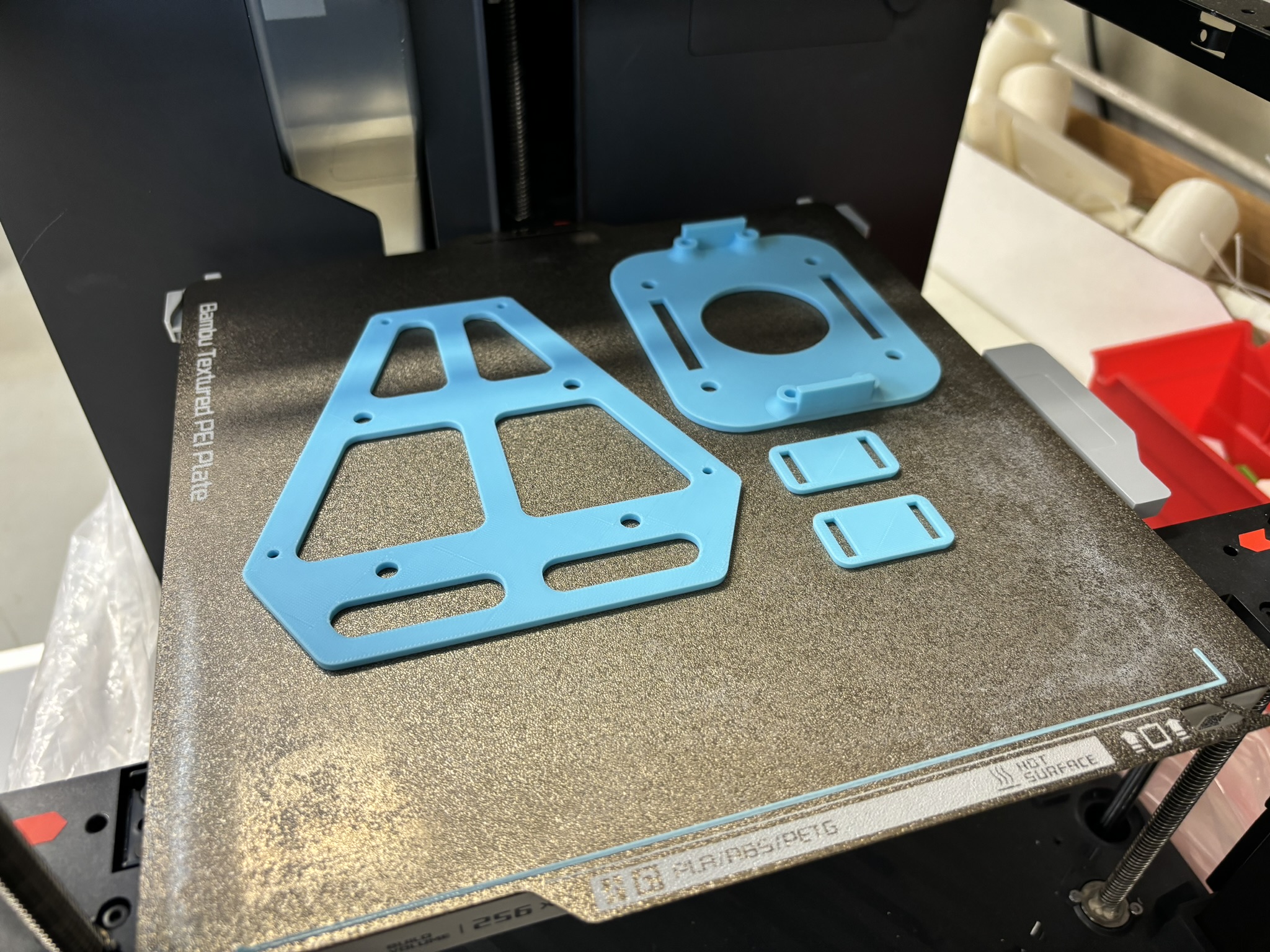
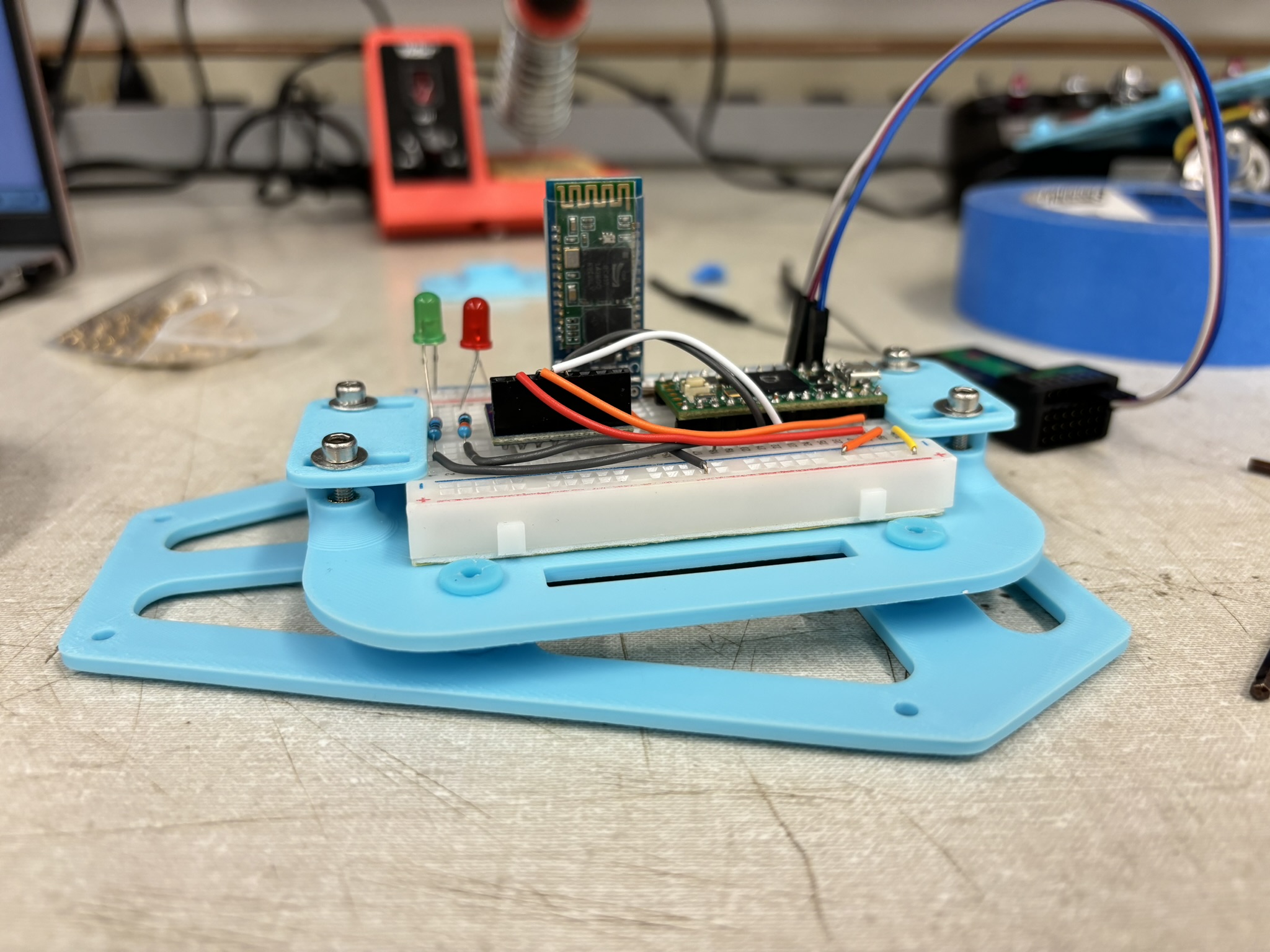
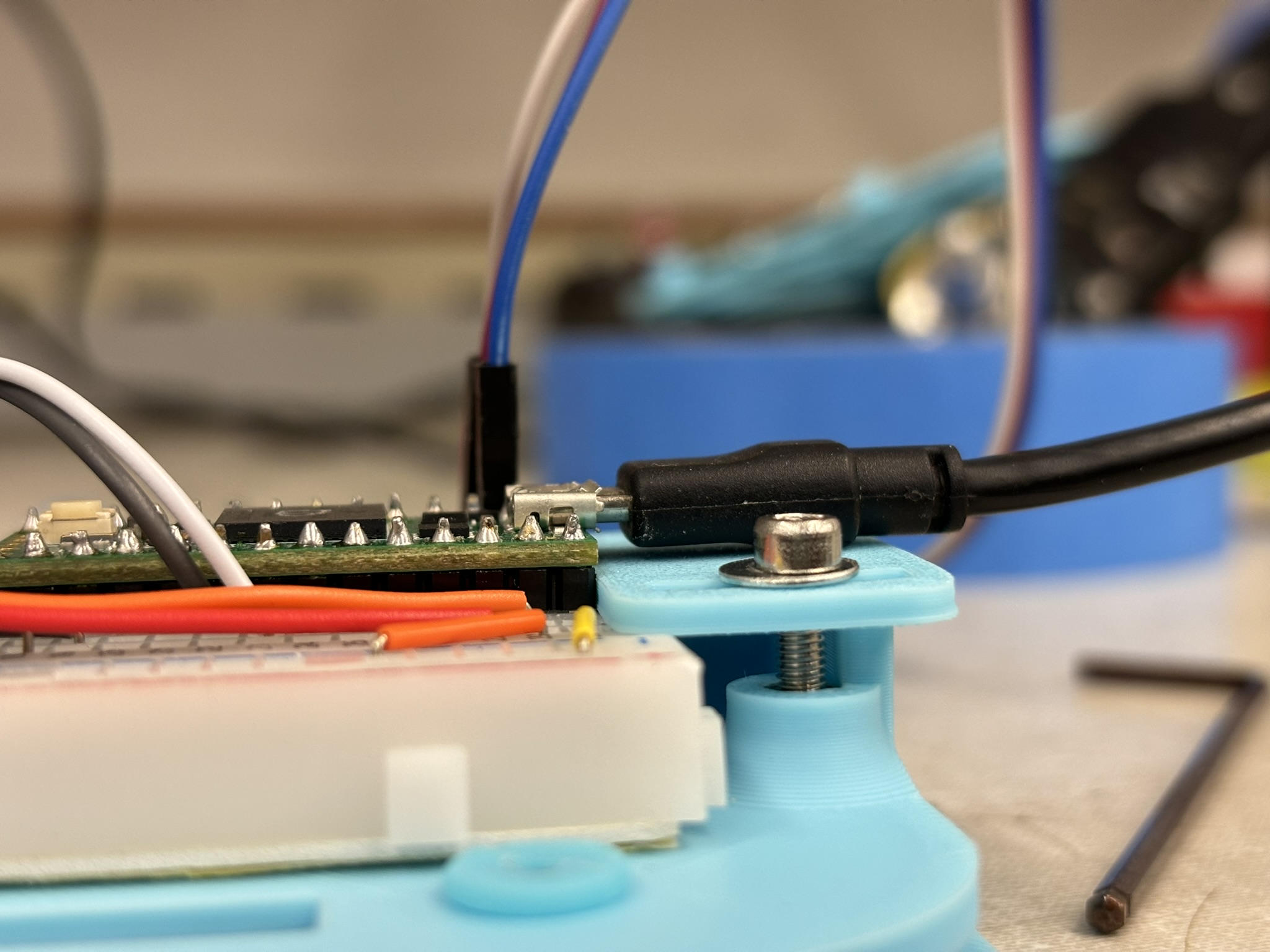
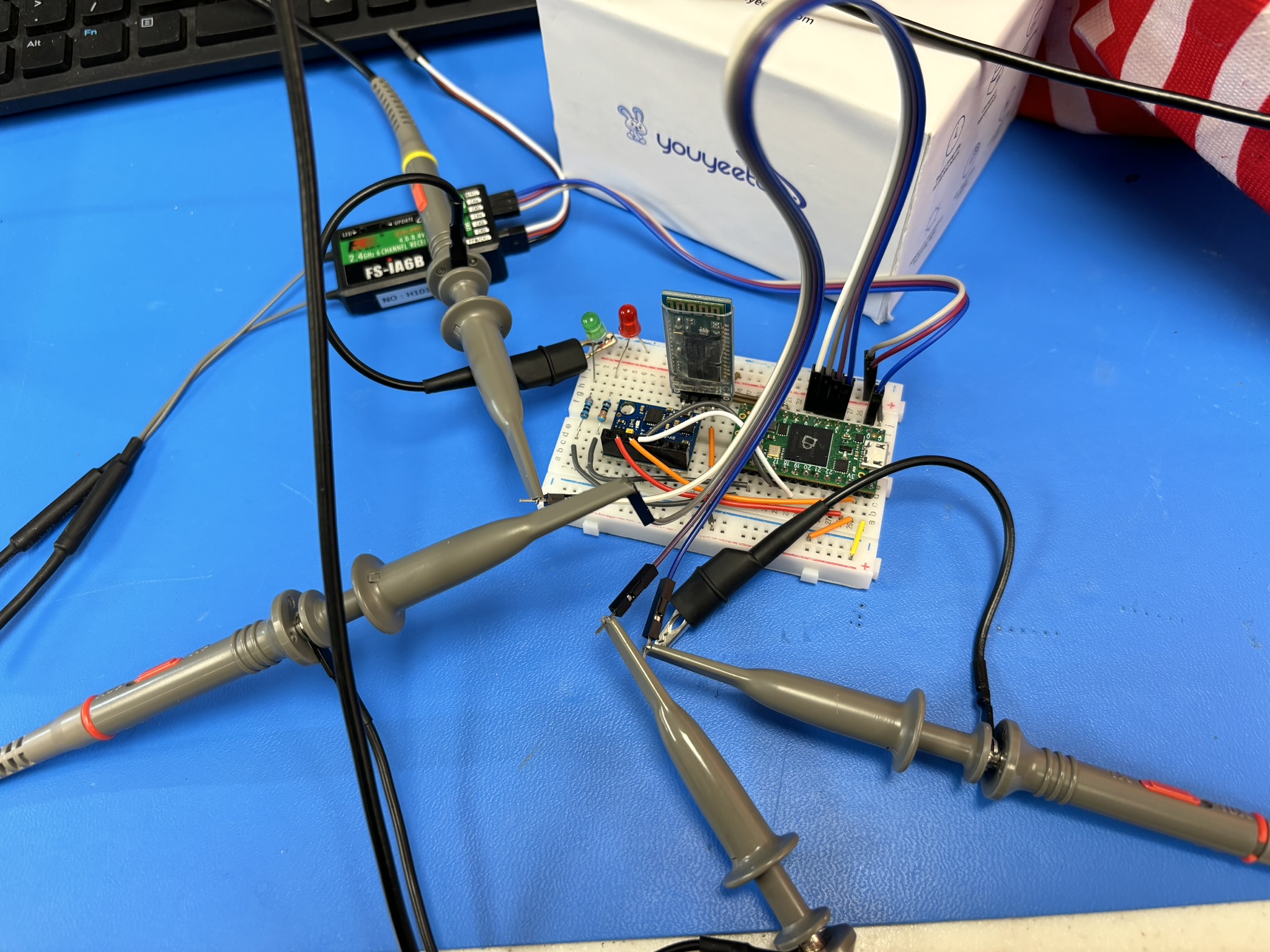
It took me so long to figure out why they are using timer interrupt to control the motor output and other things. I can’t find any material that is talking about how to output proper signals to ESC. Then finally I found a person was using Teensy to build a flight controller, and he was using port manupulation to output precise PWM signal simutaneously. Now, the last puzzle was found.
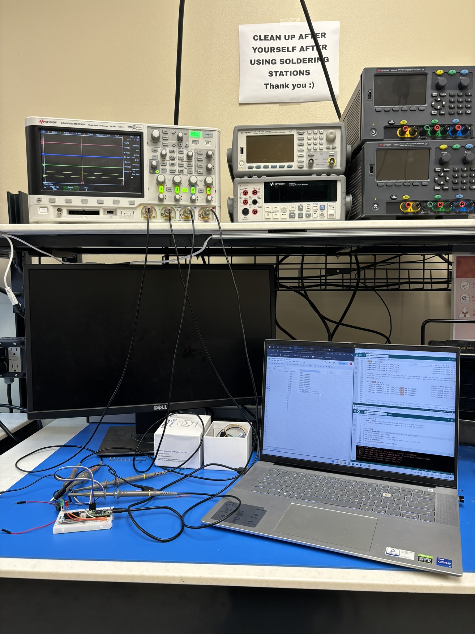
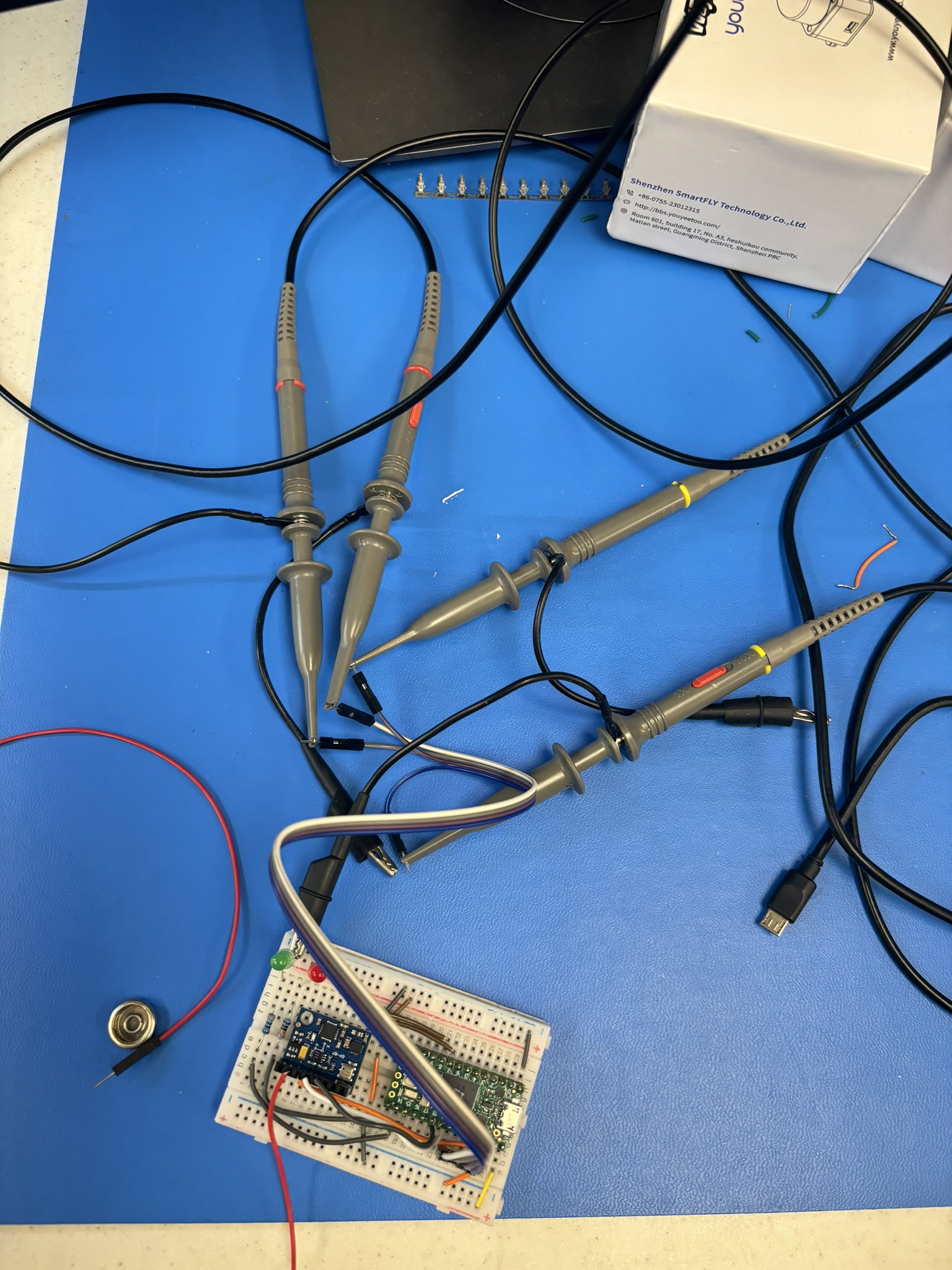
In June, after I finished the balance bot project, I decided to resume tuning. This time I went straight for the cascade PID. I was trying to find the transfer function of the drone to find the PID in Simulink, but there’s no way I could find the gain K. The rotation axis has to go through the CG, which is impractical, so I can only work with the inverted pendulum model.
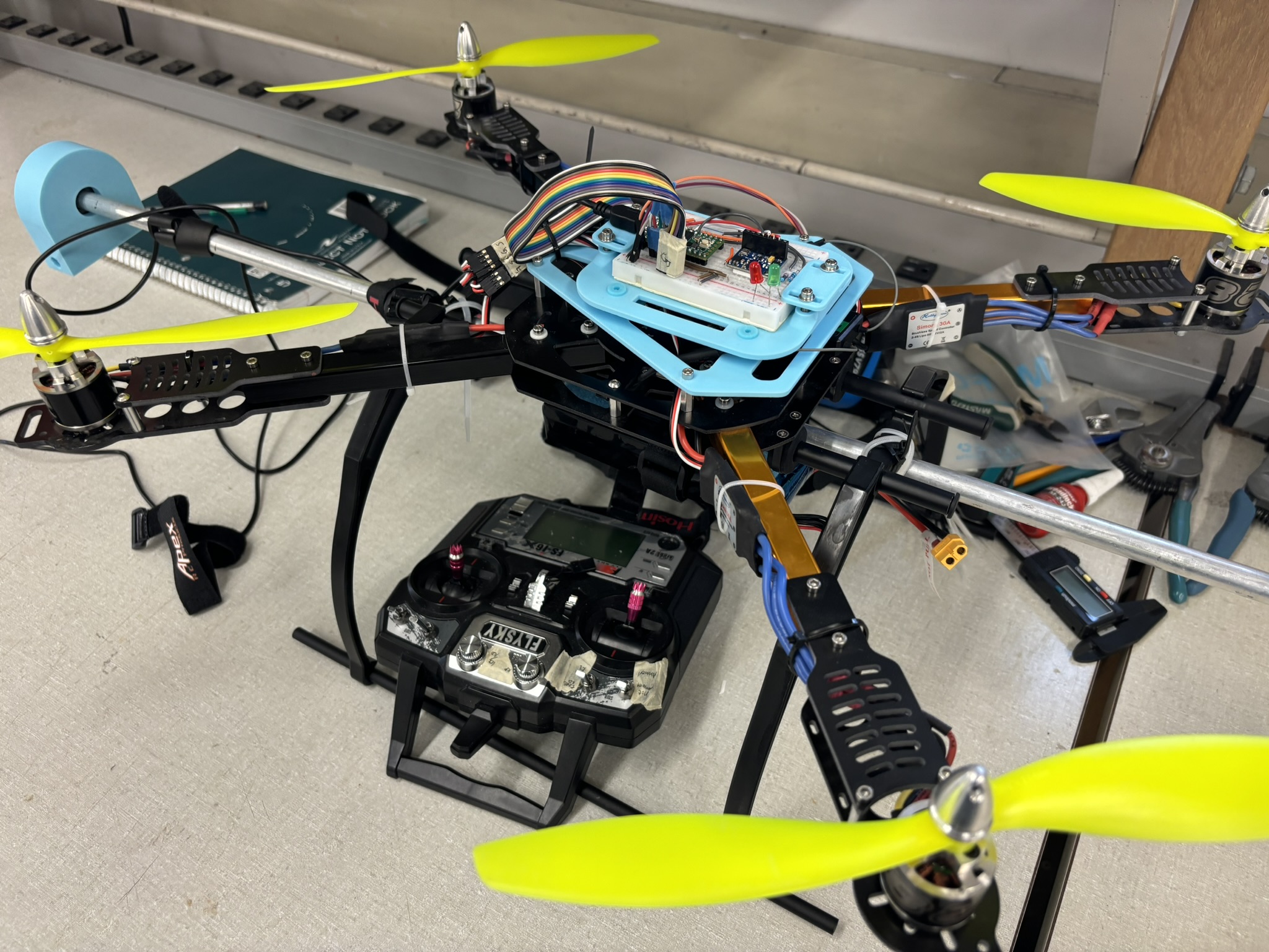
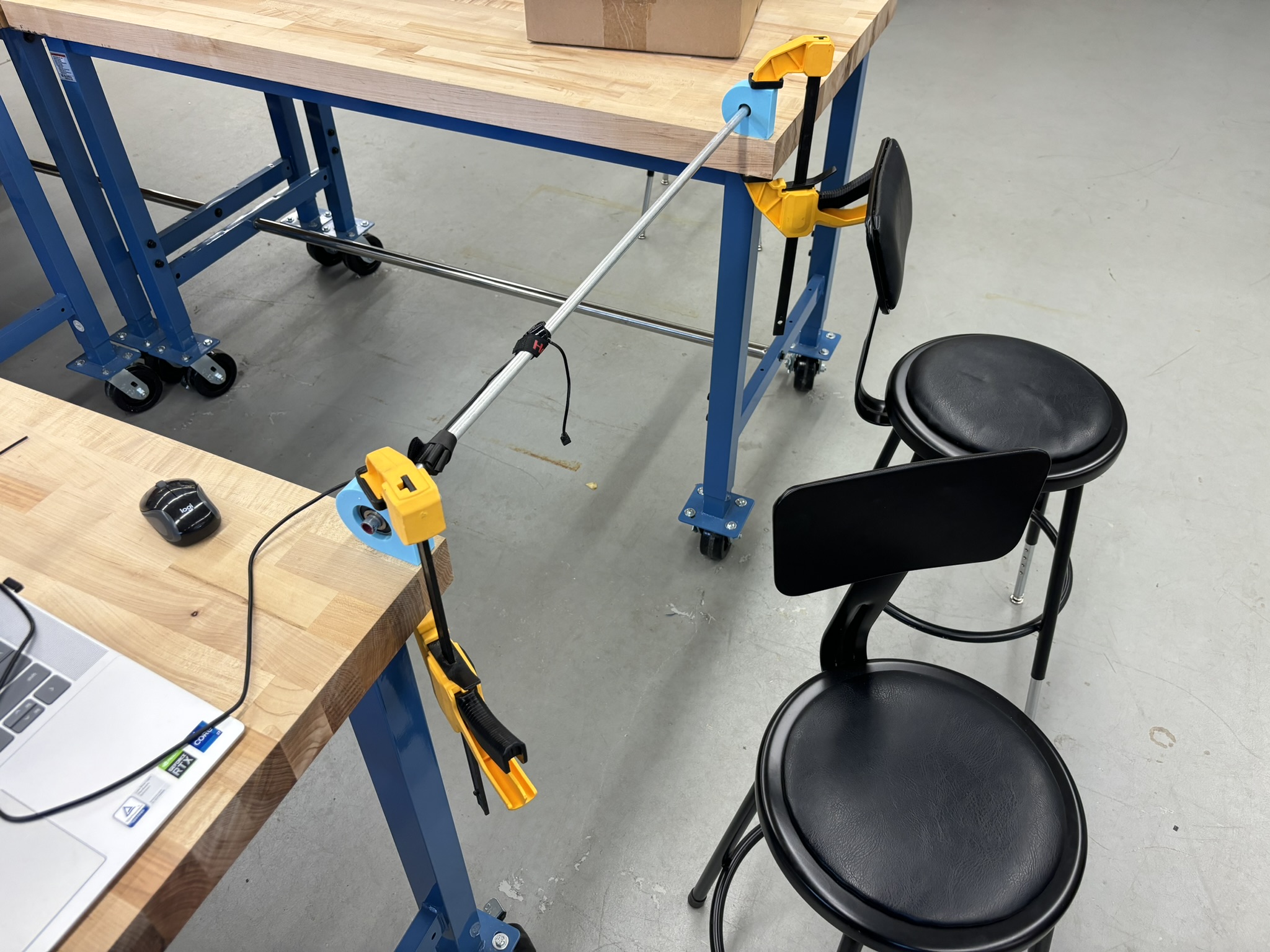
So I started with the angular speed control, and then the angle control. It performs wheel in the inverted pendulum model, but I don’t know how was that going to work in the free rigid body rotation model.
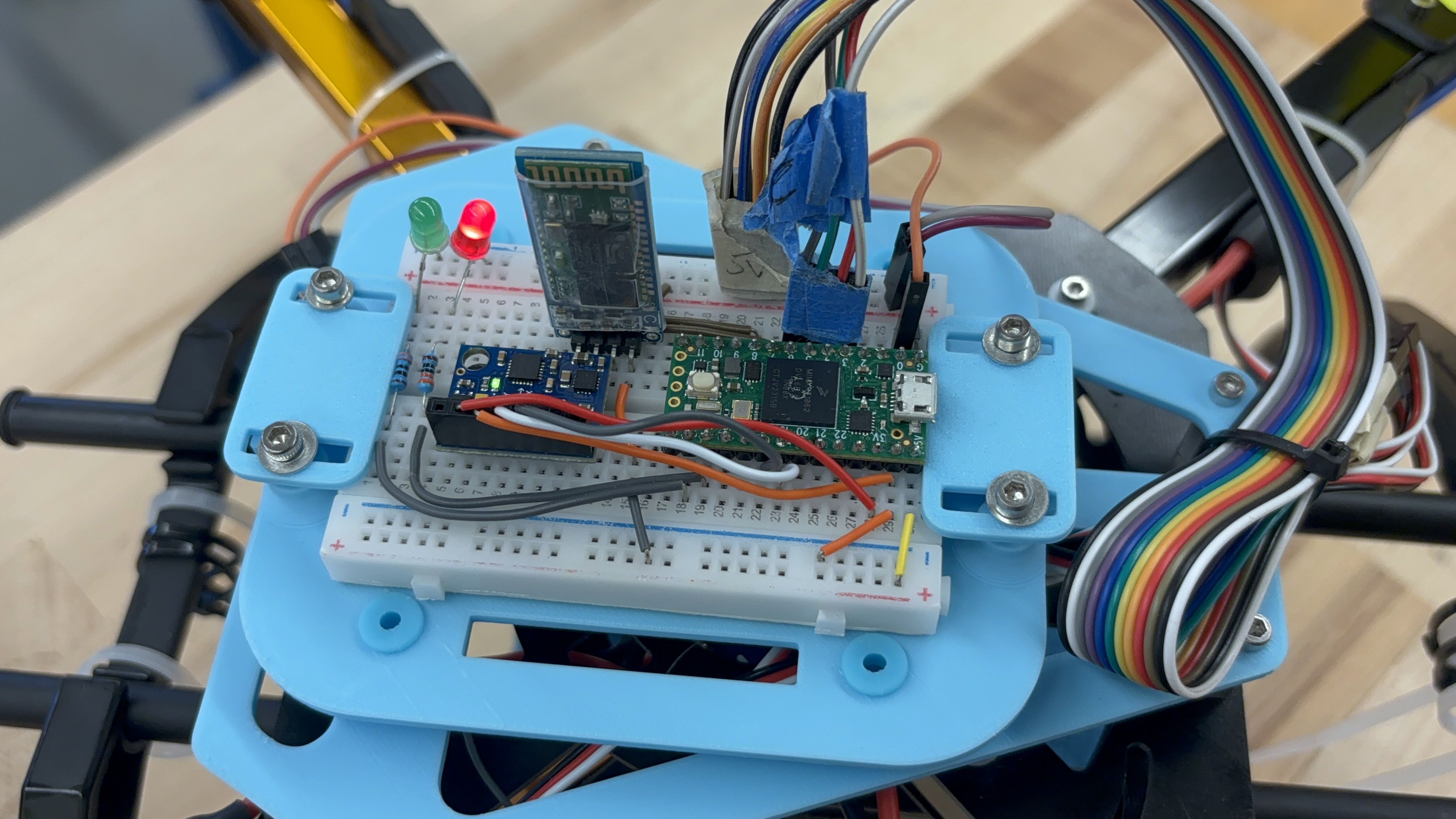
Not armed: Red LED on.
Armed: Green LED on.
The start-up sequence:
- Initialize the ESC, so they won’t get into the calibration mode. Red LED is constantly on. The green LED flashes once when finished.
- Communication set up. The green LED flashes twice when finished.
- If the transmitter is in the Armed position, Red LED flashes.
- IMU Calibration. Red LED is constantly on. The green LED flashes three times when finished.
- Set the ESC pins again. The green LED flashes four times when finished.
- The green LED fast flashes four times, it means it’s ready to go.
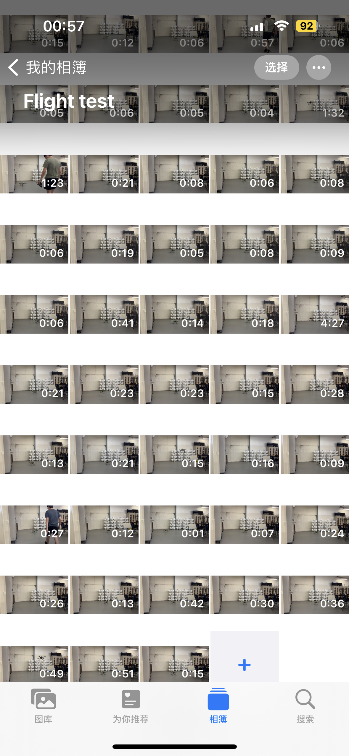
Future Improvement
- Lock the heading with the magnetometer and tilt compensation.
- Lock the height with the barometer, vertical speed in the inertial frame (solved), and Kalman Filter.
- Tune the PIDs more precisely.
- Lost head control mode (facing at take-off is the front).
- Introduce GPS.
- GPS position locking.
- GPS return to home.