I. Intro
Date: April – May 2023
Everything started when Prof. Rose asked me about the aluminum materials I got. He wanted to use them as the heat sink of the super bright LED. After the heat sinks were done, I saw they were using Arduino to control the LED and wanted to put them on the DJI Mavic 2 Pro. That’s super heavy, so I built an astable LM555 timer and used a small LED to demonstrate the signal. Someone was laughing at me and asked how was that small LED can be seen from three statue miles. I didn’t answer because I know it would be a waste of time.
II. LM555 Theory
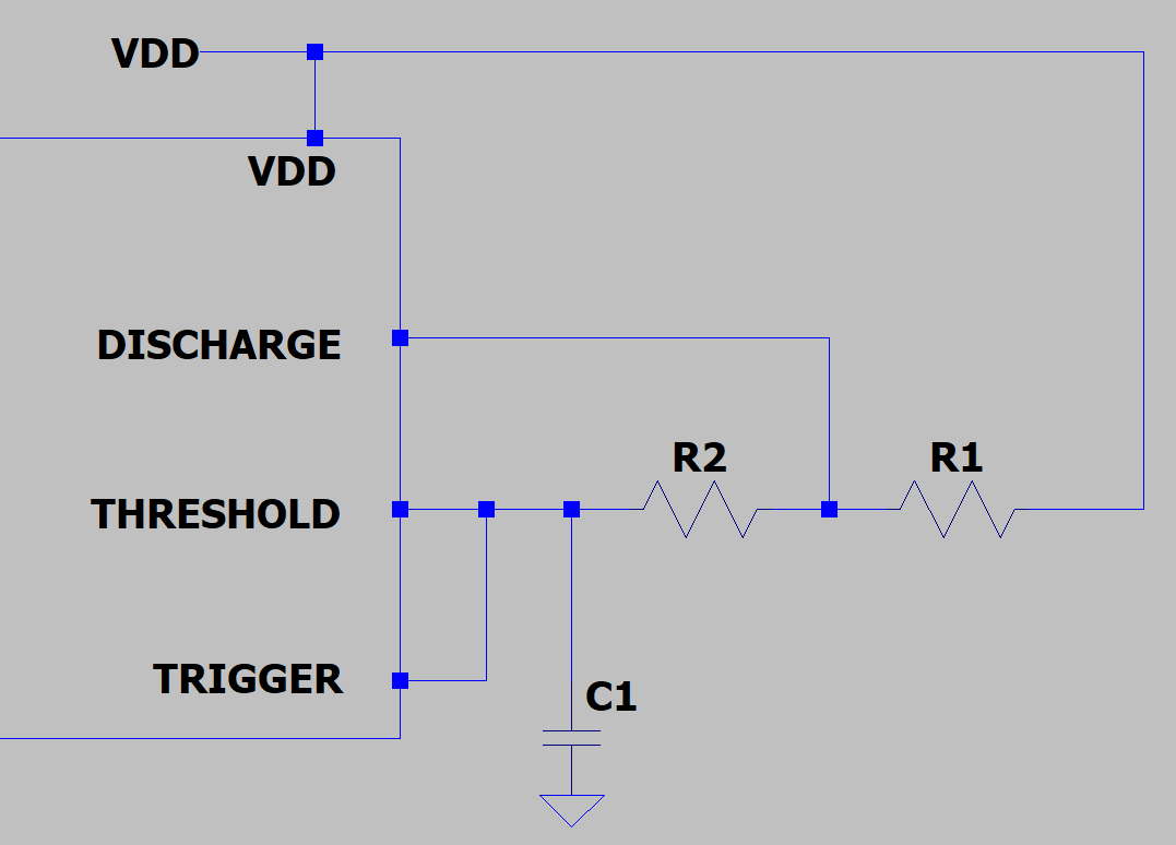
LM555 has three 5k Ohms resisters that divide the Vdd into GND, 1/3Vdd, and 2/3Vdd, and two compartors compare the voltage between 1/3Vdd and Trigger, 2/3Vdd and Threshold.
- When the voltage of the TRIGGER pin is below 1/3Vdd, SR latch will set, and the output is high.
- When the voltage of the THRESHOLD pin is above 2/3Vdd, SR latch will reset, and the output is low.
| Time | TRIG | Latch: S | THRES | Latch: R | DISC | Vout |
| t0 | 0 | T | 0 | F | F | T |
| t1 | <1/3Vdd | T | <1/3Vdd | F | F | T |
| t2 | 1/3 ~ 2/3 | F | 1/3 ~ 2/3 | F | F | T |
| t3 | >2/3Vdd | F | >2/3Vdd | T | T | F |
| t4 | 1/3 ~ 2/3 | F | 1/3 ~ 2/3 | F | T | F |
| t5 | <1/3Vdd | T | <1/3Vdd | F | F | T |
When C1 is charging (output=HIGH), the current is charging through R1 and R2. When C1 is discharging (output=LOW), the current is going through R2.
If the charging time is t1, by using the RC charging equation, we can get: t1=ln(2) * (R1+R2)*C1.
If the discharging time is t2, we can get: t2=ln(2)*R2*C1.
t1+t2 is the period, and t1/(t1+t2) is the duty cycle. However, the minimum duty cycle we can get is 50% because R2 influences both charging and discharging time. We need a diode to lower the duty cycle below 50%. If we can skip R2 when it’s charging, only R1 can affect the charging time.
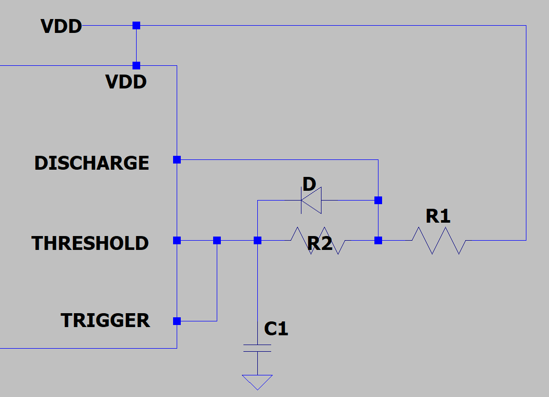
Now t1=ln(2)*R1*C1, t2=ln(2)*R2*C1.
If we want the flight light to stay on for 10 ms and flash once a second (frequency is 1Hz), t1=0.01s, and t2=0.99s. After choosing the closest values, the circuit is determined.
Reference: 555 Theory.
III. Material Preparation
A. Aluminum Heat Sink
Date: 04/09/2023
Prof. Rose sent me the dimensions of the LED.
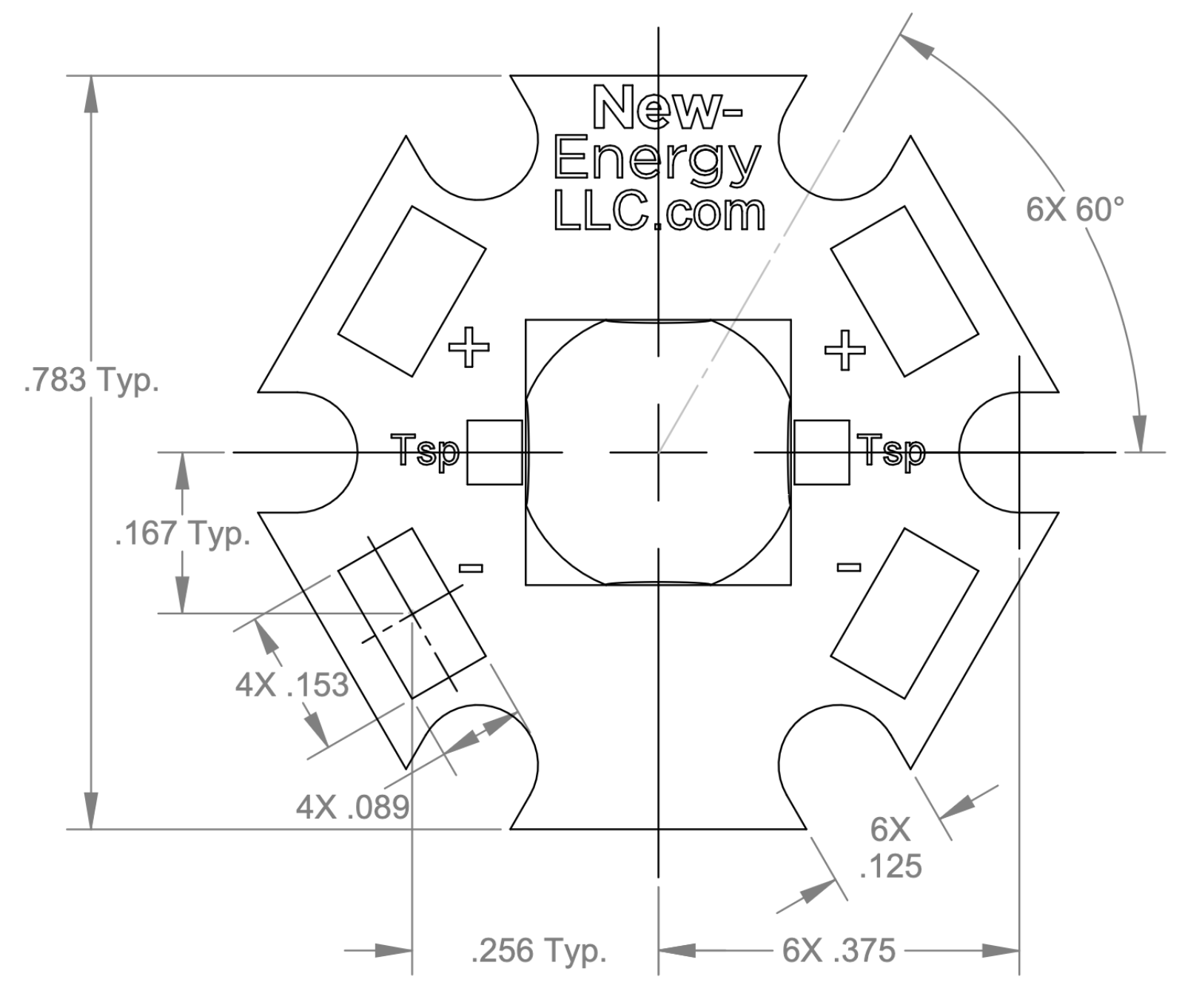
Based on that information, I quickly made the sketch of the piece I needed to make.
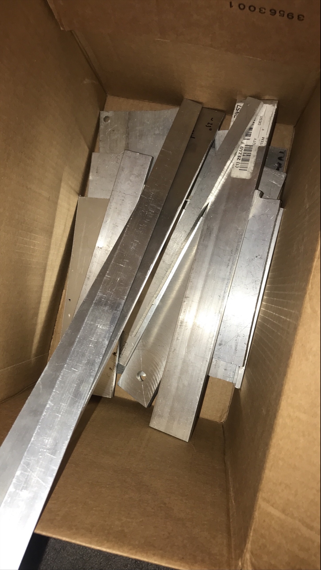
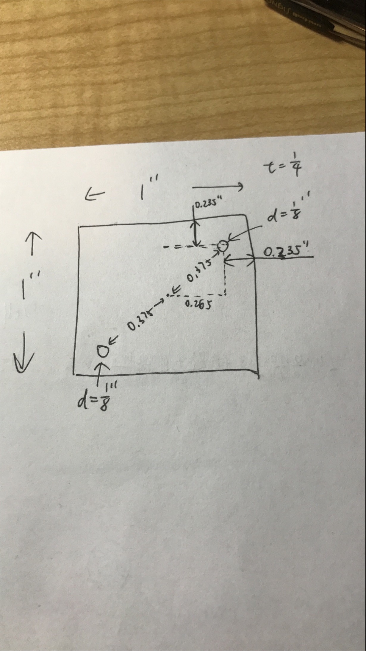
I chose a 1/4” thick and 1” wide aluminum bar. Using trigonometry, I can calculate the position of the holes. The dimensions were in the picture.
On the second day, I brought the bar to the machine shop:
- First, I marked the 1” sections on the bar.
- I picked the parallel carefully so that the drill bit wouldn’t hurt the parallels. The parallels were less than 0.1725” thick (0.235-1/2 * 1/8).
- Then I used edge finder to define the zero, replace the drill bit, and moved the drill bit to the position based on the XY information on the display.
- I did the top row first. When Y was 0.235”, I drill the holes at X=0.235”, 1.235”, 2.235”, and so on.
- Then I adjusted the Y to 0.765”, drill the holes at X=0.765”, 1.765”, 2.765”, and so on.
- After 14 sections were made (I had to relocate the material and redefine the zero with the edge finder), I cut them in pieces with the bandsaw.
- Finally, I used a file and the deburring tool to make them smoother.
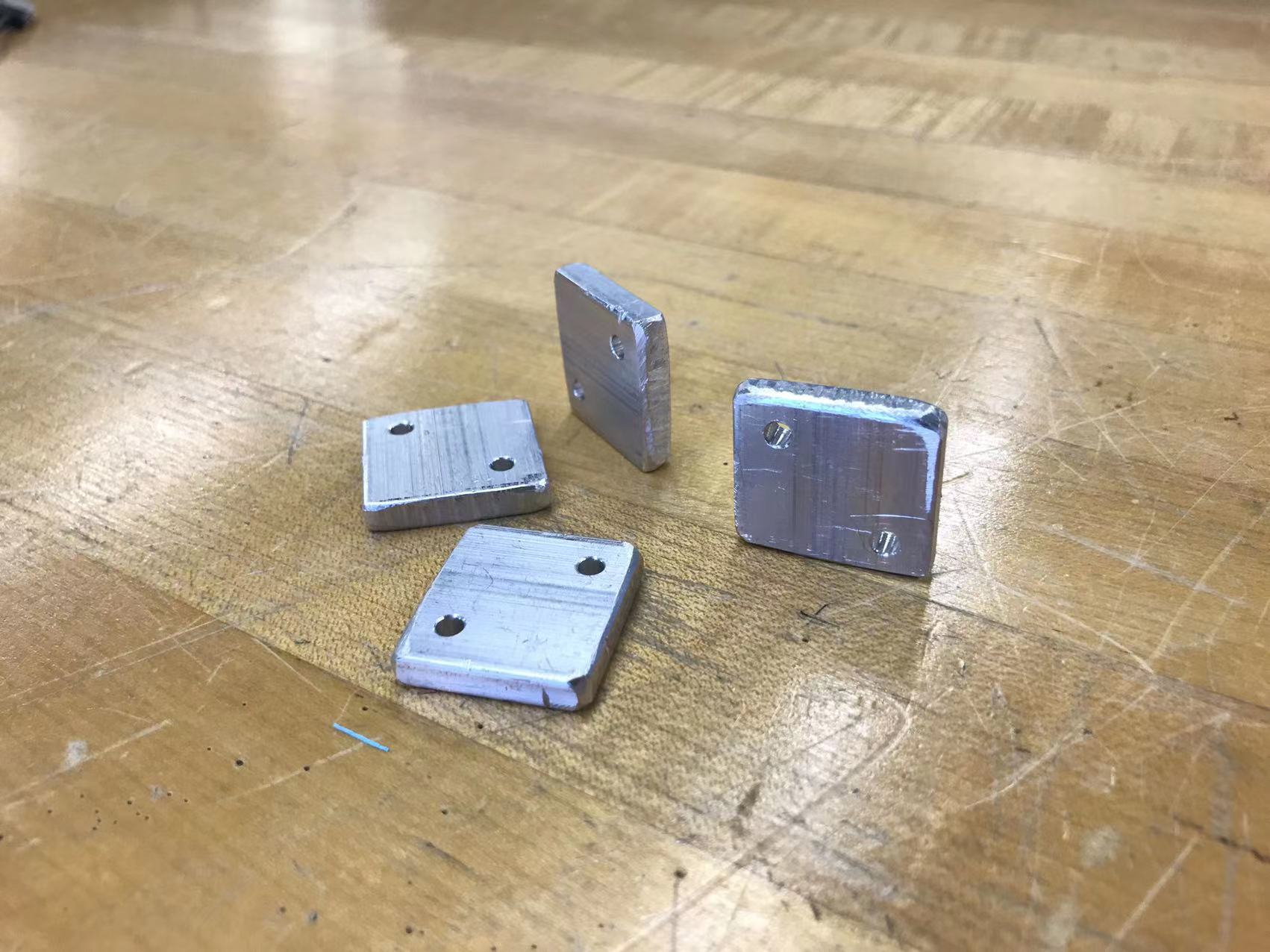
B. Control Circuit
1. Timing Circuit
With the equations: 10ms=t1=ln(2)*R1*C1, 990ms=t2=ln(2)*R2*C1, I chose C1=10microF, R1=1500Ohms, R2=150kOhm.
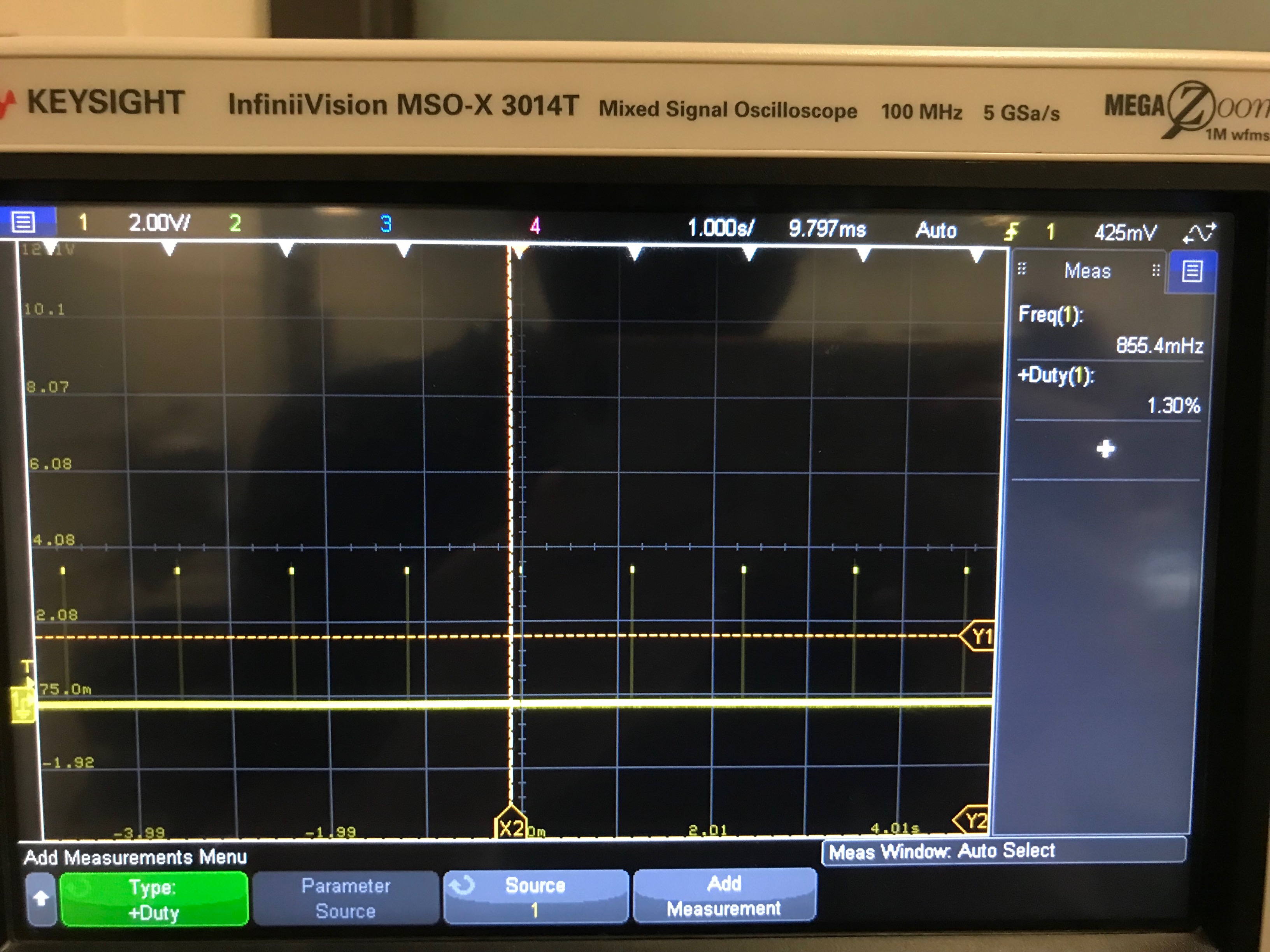
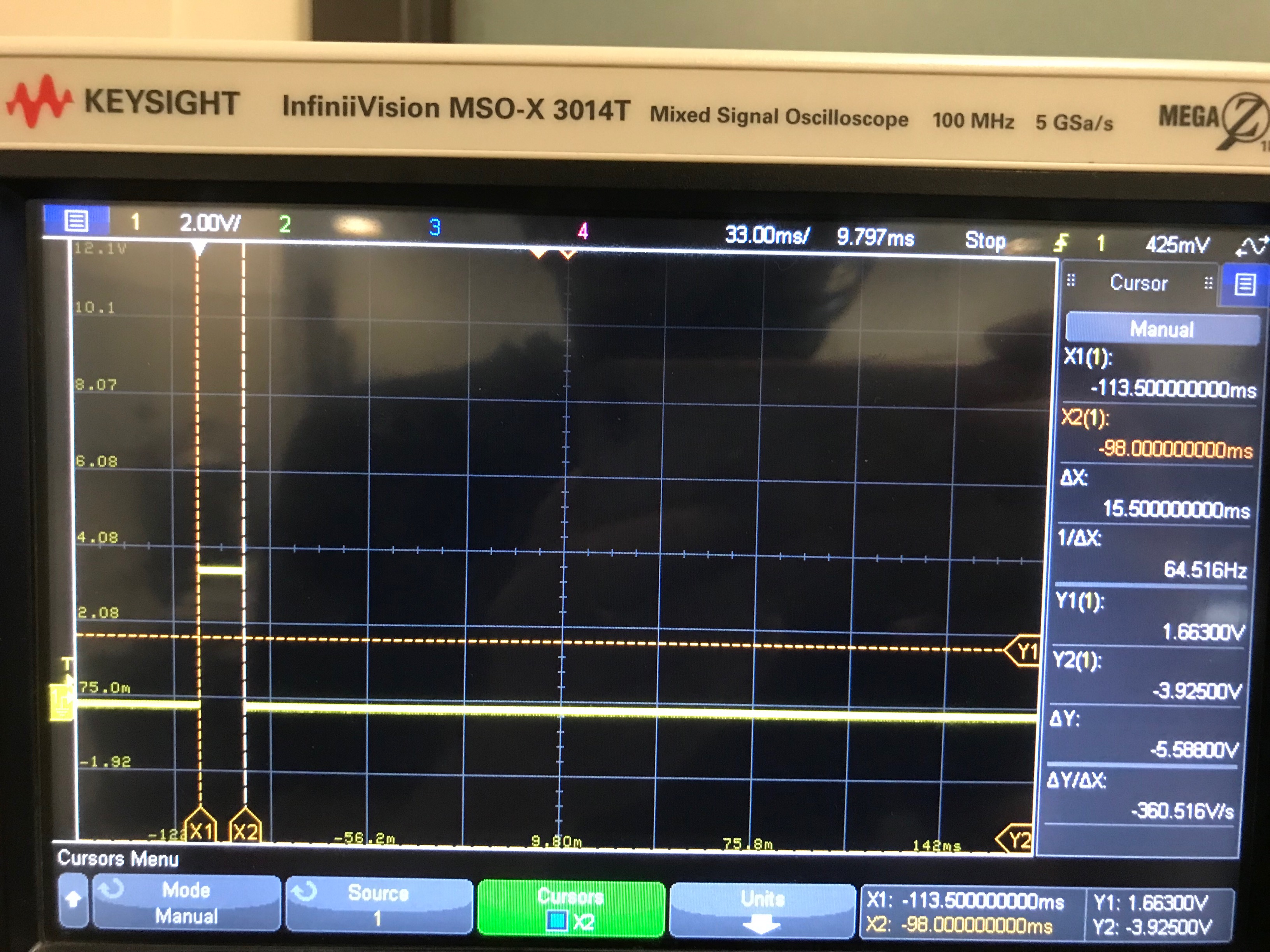
Then I used a potentiometer in series with R1 and a lower value for R2 to adjust the frequency and the duty cycle.
| C1 (uF) | R1 (Ohms) | R2 (Ohms) | Frequency (Hz) | Duty Cycle (%) | |
| Expected Value | 10 | 1442.7 | 142826.8 | 1 | 1 |
| Initially Used Value | 10 | 1500 | 150,000 | 0.8554 (mea) | 1.3 (mea) |
| Final Used Value in Prototype | 10 | 1000 | 133,000 | 0.9568 (mea) | 1.045 (mea) |
So the final values were: C1=10uF, R1=1000 Ohms, R2=100kOhms + 33kOhms
2. DC-DC Step-Up Board
I found this tiny DC-to-DC step-up circuit board on Pololu. From the graph “Maximum continuous output current”, it can output more than 2A when the output voltage is 12V. This is sufficient to drive the LED. Since the size of the constant current sources are so big, and the constant voltage source also works, I decided to use a voltage source.
3. Driver
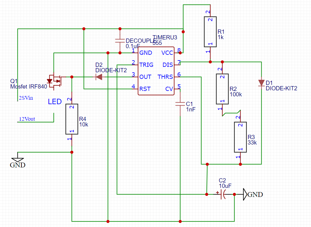
The LED is controlled by a power MOSFET (IRF840) which receives signals from the output pin of the LM555 timing circuit. Coming out from the timing circuit output, the current will go through a diode that protects the timing circuit, then a 10k Ohms pull-down resistor is connected to the ground. The circuit below doesn’t include the DC-DC step-up circuit board.
C. Prototyping
Since I was very familiar with the circuit, it was built very quickly. The components were provided by EE Shop for free. I picked the blue LED just because it’s a BLUE LED.
(I am still trying to figure out how to adjust the video size on WordPress, it seems like none of the solution works. You can hold “CTRL” and use the mouse wheel to adjust the size).
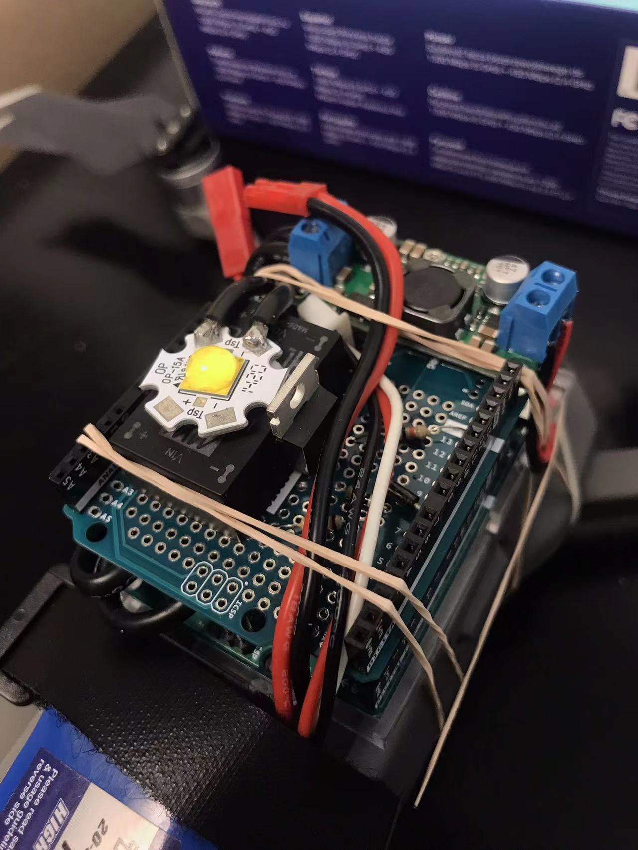
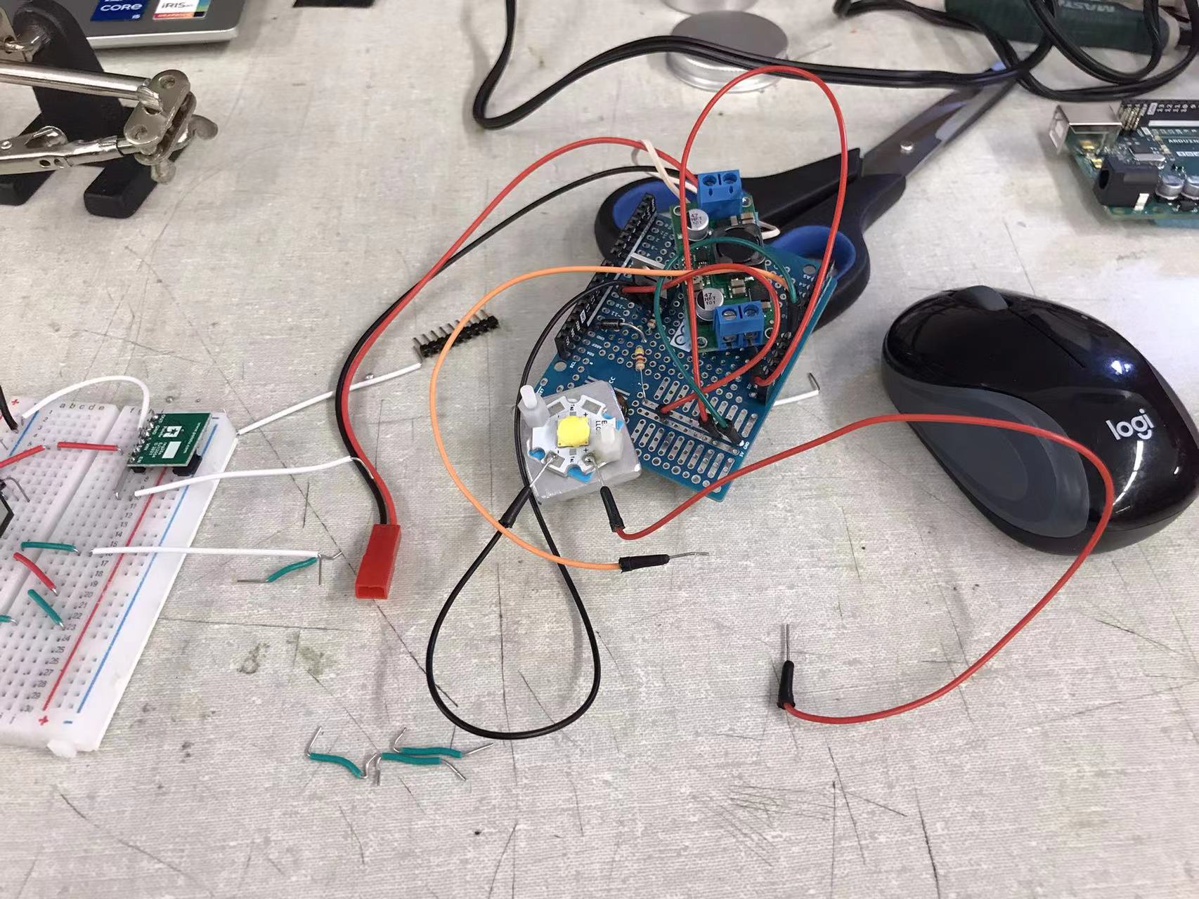
IV. PCB Design
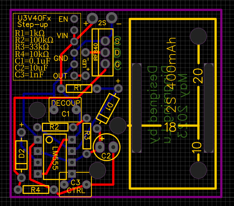
After the prototype tests were done, the circuit schematic was drawn, and it was converted into a PCB file.
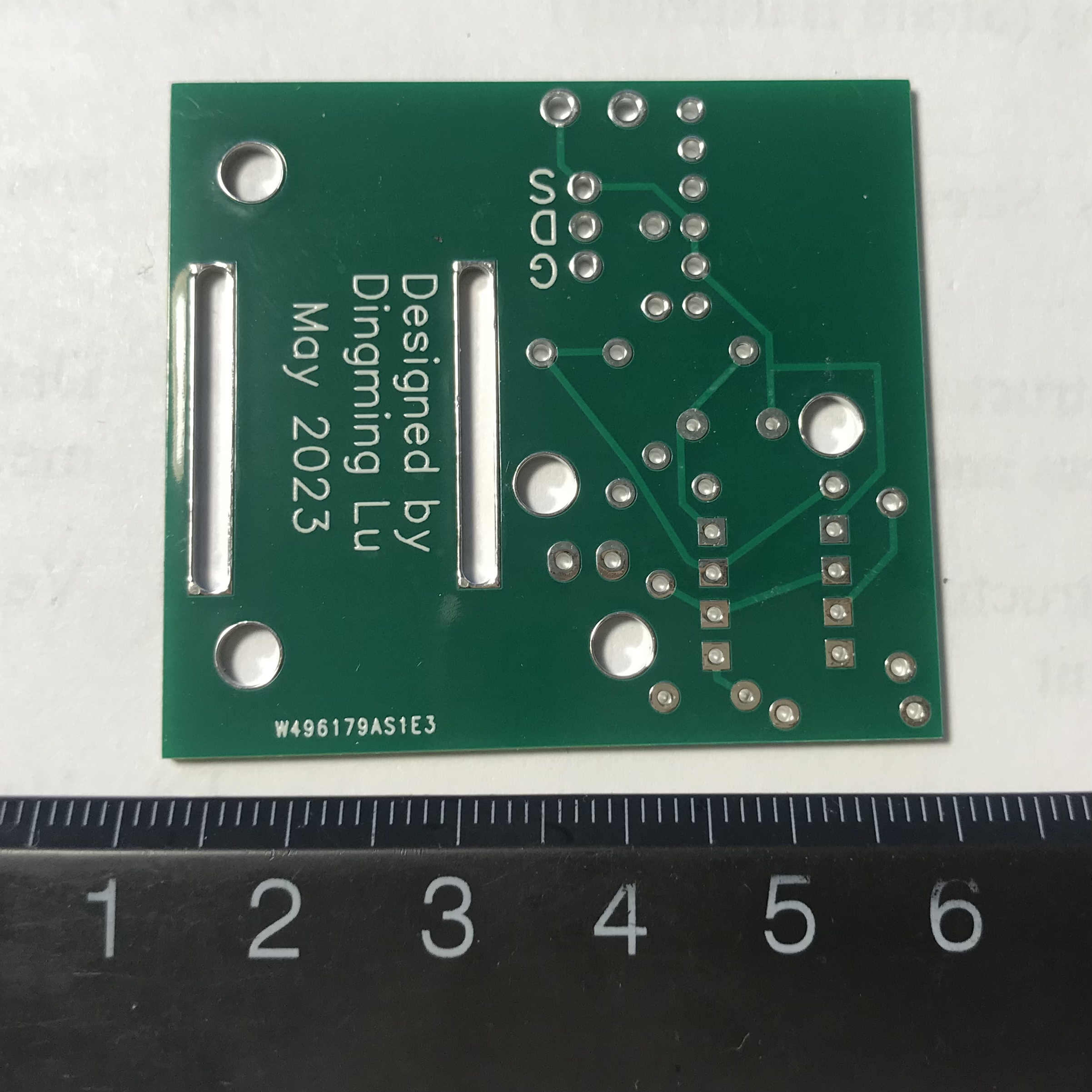
- Plating Through Hole (PTH): there is copper covered in the borehole wall. The hole was drilled before the chemical reaction.
- Non-Plating Through Hole (NPTH): there is no copper covered in the borehole wall. The hole was drilled after the chemical reaction.
Key points:
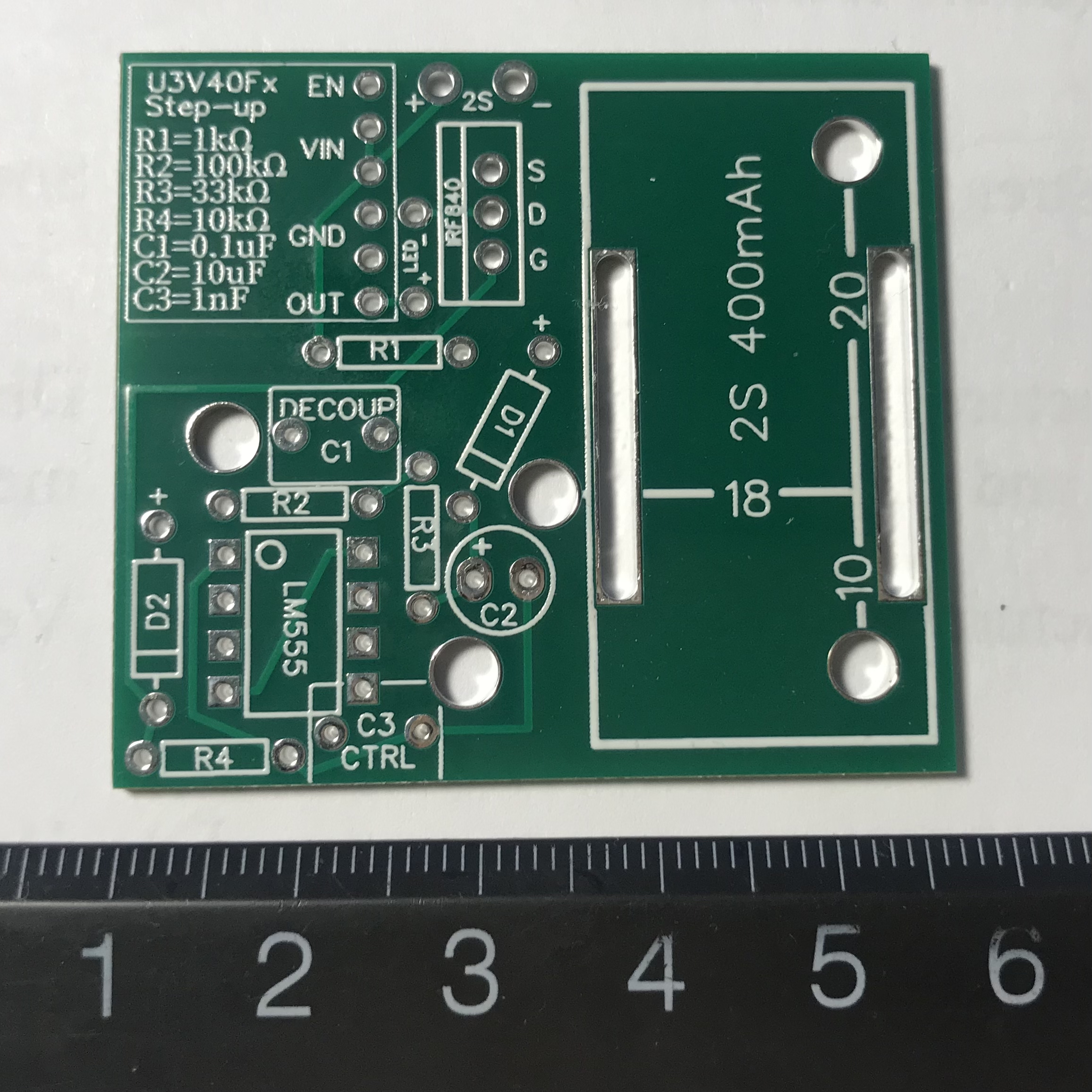
- To reduce the size of the board, I decided to use nylon hex-spacers to elevate the LED and its heat sink high and put the LM555 under the heat sink. The two largest circles near the LM555 were reserved for the spacer.
- I put the DC-DC step-up voltage source on the upper left corner. The pins were 0.1” between each other.
- I decided to use this small 400mAh 2S Li-Po battery, just because it’s small and light.
- I also reserved the holes for screwed installation. The dimensions are at the battery installation area in millimeters.
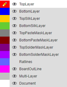
V. PCB Assembly
The PCB finally arrived. It took forever. The package stayed near Chicago Illinois for two weeks, and it went to Ohio. Why couldn’t USPS just send the package directly to Indiana? That’s only about a 3-hour drive from Chicago to Purdue, and I had to wait for more than two weeks. Ridiculous.
The assembly was easy, just made sure every component was in the right direction. Plugin the battery, and it worked. Later on I realized the aluminum heat sink may not be necessary because LED was not even warm at all. This was because of the 10ms short on time.
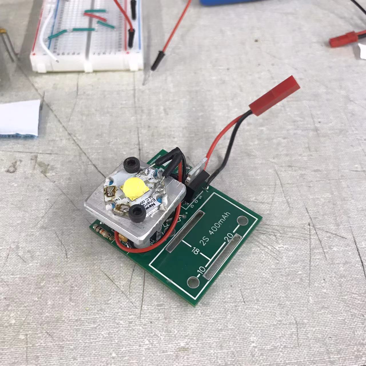
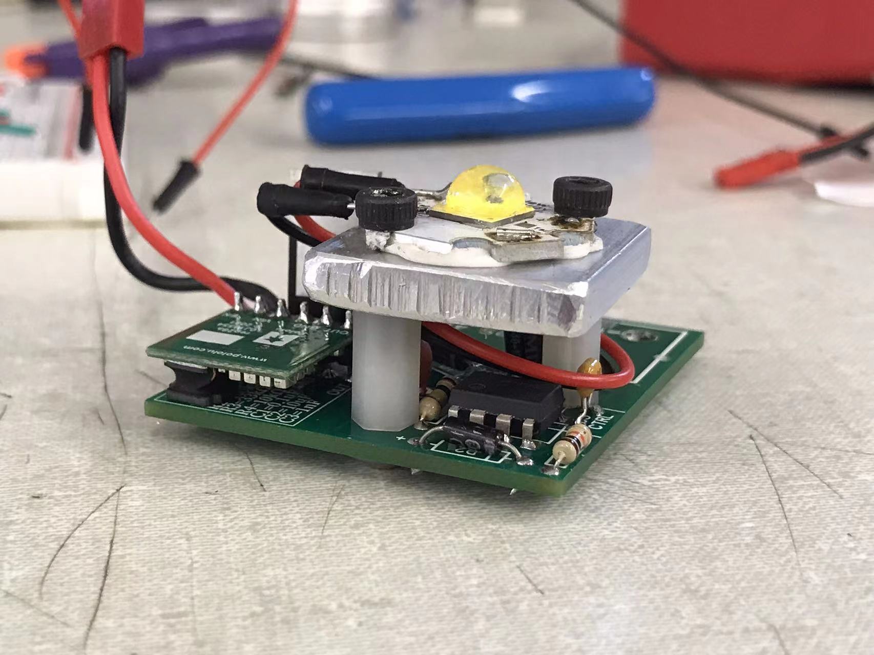
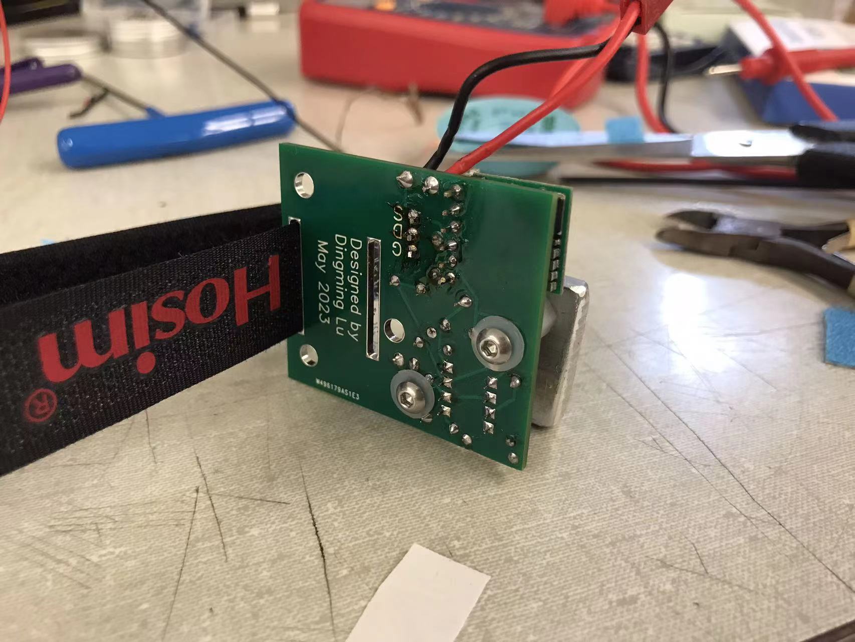
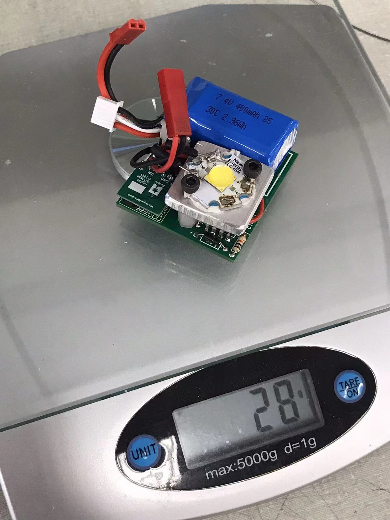
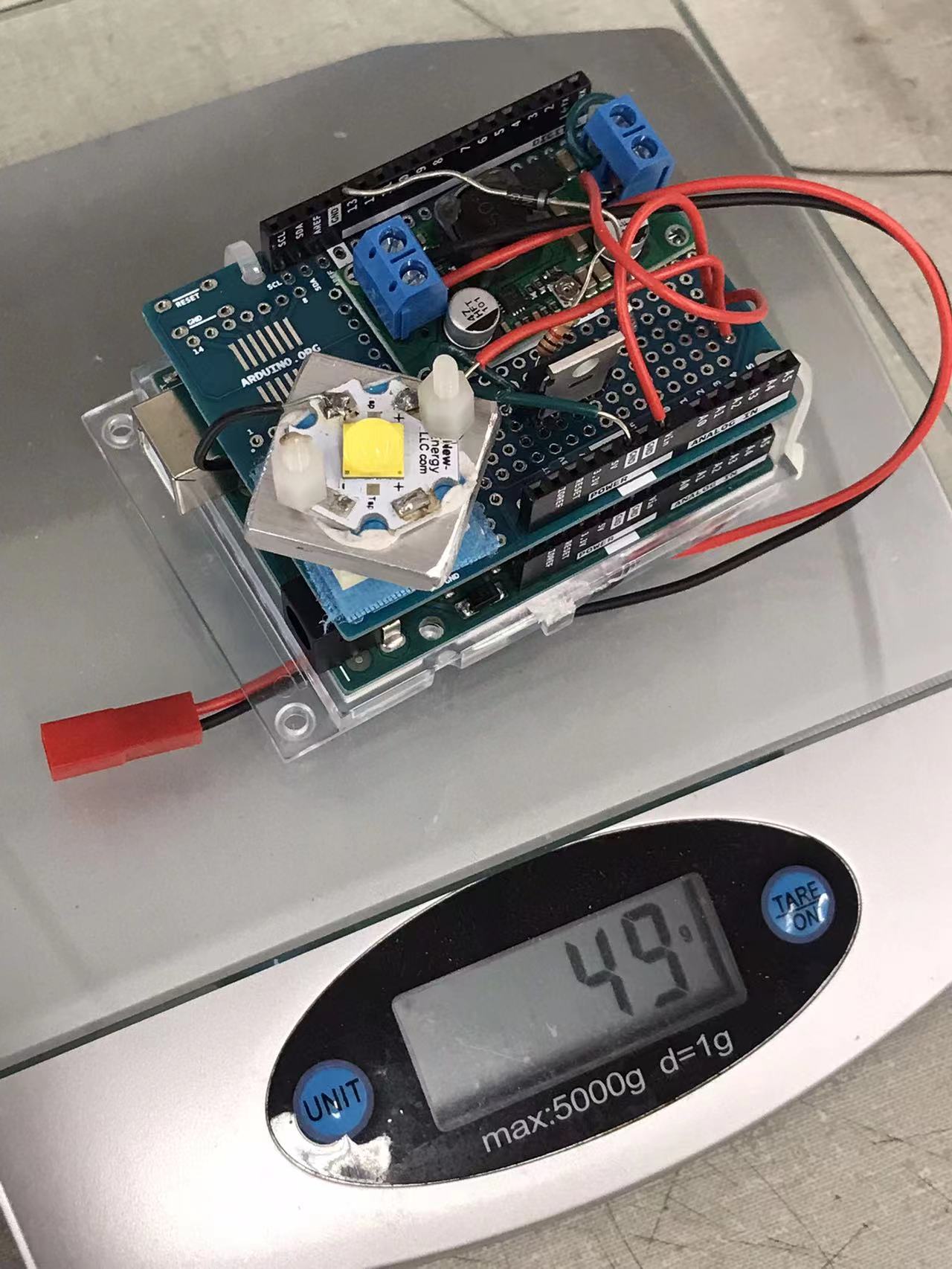
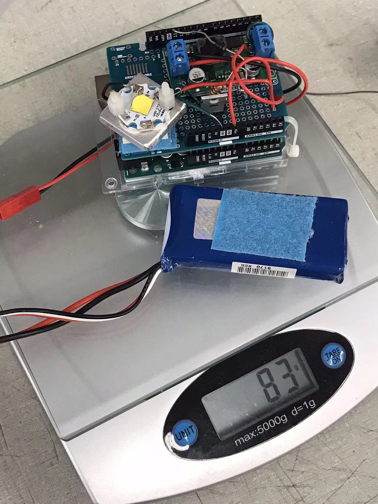
Mass comparison: it’s only 28/83=33.7% of the Arduino version.
