I. Intro
Date: August 2022 – Present
Skateboards are hard to maneuver, countless gaps are trying to tip over you, and I play caster board (rip stick) much better than a four-wheel skateboard. I want to find a solution to travel faster and easier on campus…
Before everything starts on this page, I will list all the problems I am facing right now (But you can also start with the next main section to see the building process, and then come back to the problems). They are either because I don’t have time to do them, I don’t know how to solve them, or I don’t have enough funds to do them. Then I will put everything I did and I would do.
(So what I was doing during the summer of 2023 you may ask. I was making the LM555 flight light (April – end of May), learning Arduino (May – July), Solidworks (May – July and not finished yet), building the second caster board (May – June), taking a summer course (June – August), building the server (July – August and not finished yet), working on the flight controller (June – August and not finished yet). I have been sitting in front of my computer and only building this website for hours and hours a day, and now the fall semester is starting. )
Problems I am facing right now:
- In the coming up semester, I have 21 credit hours and two jobs. So I will be super busy. I probably have to continue working on it in December.
- Kinematics: After I found out the first prototype didn’t work as I expected, I realized the kinematics is much more complicated than I thought. The kinematics is mainly focusing on the caster. The key is to push and pull the front and rear board side to side causing the caster to rotate about 45 degrees relative to the board, meanwhile, the rotation of the casters is causing the board to rise and gain some potential energy. Then let the board fall back to its original position by simply standing on the board (or pulling or pushing the board into the opposite position). Since there is no slipping on the wheels, and when the board is falling, the caster will transfer the vertical falling motion (from potential energy) into the forward motion (kinetic energy).
- (Continued) To make the kinematics work, can I simply scale the caster board from the market product? I have not tried that yet. Think about this thought experiment:
- To overcome the evil gaps on the road, the wheels have to be bigger, somewhere like the electric scooter, 8” or even higher.
- If I scale the wheels to 8”, the board and the caster would be super large.
- When the size is getting bigger, it causes two problems:
- It’s heavier, and my mass would not be much more than the mass of the board. It would be harder to control with two legs. The market caster board I am referring to is only 1.4 kg, which is only about 1.9% of my mass, and I can control it very easily. The first prototypes I made were reaching 11 kg, which was about 15% of my mass.
- It’s very high from the ground. I don’t know what would happen if I were about a foot above the ground. It has a higher center of gravity, with a heavier board and less control. I am not sure if that’s ridable (it might be?).
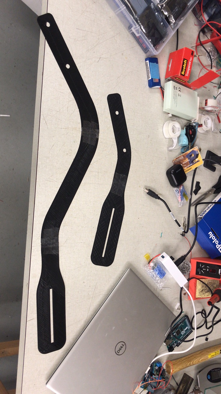
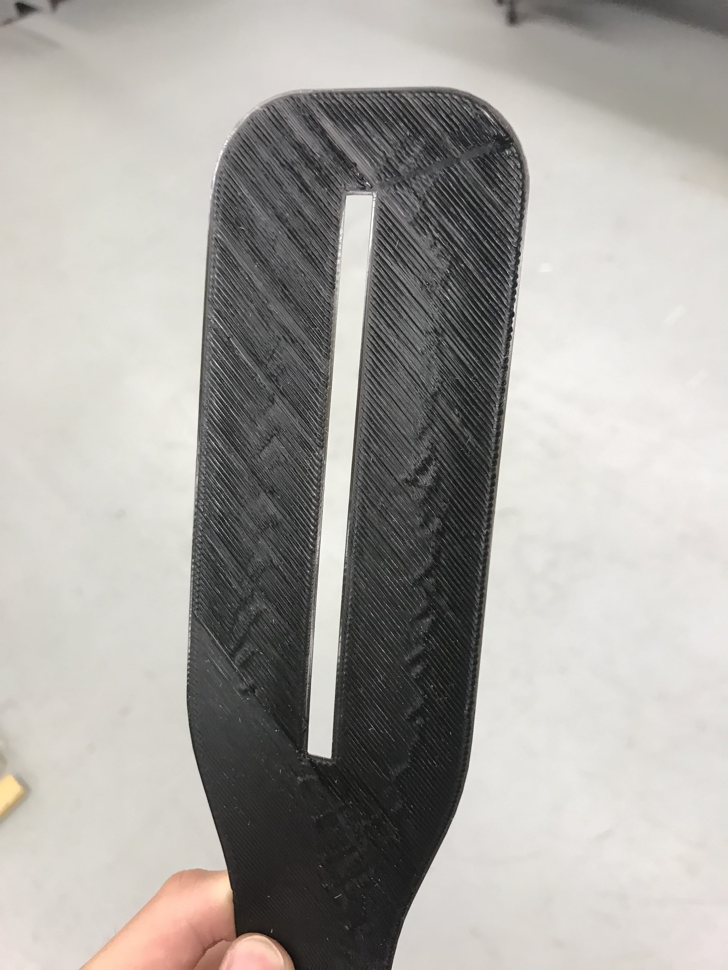
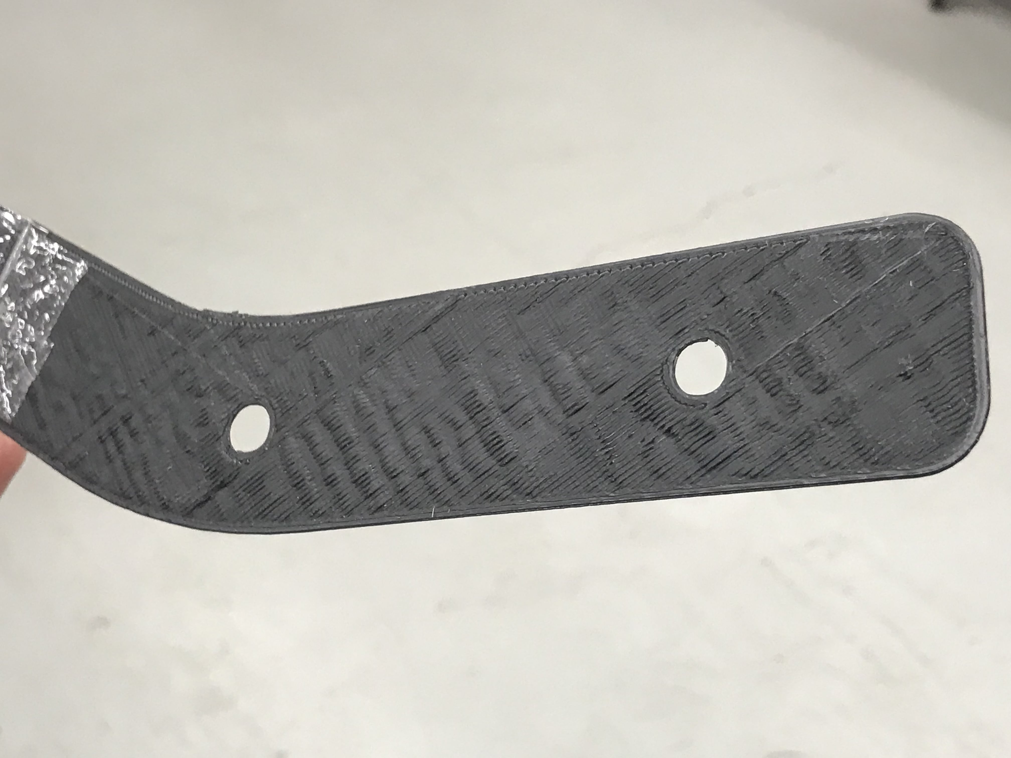
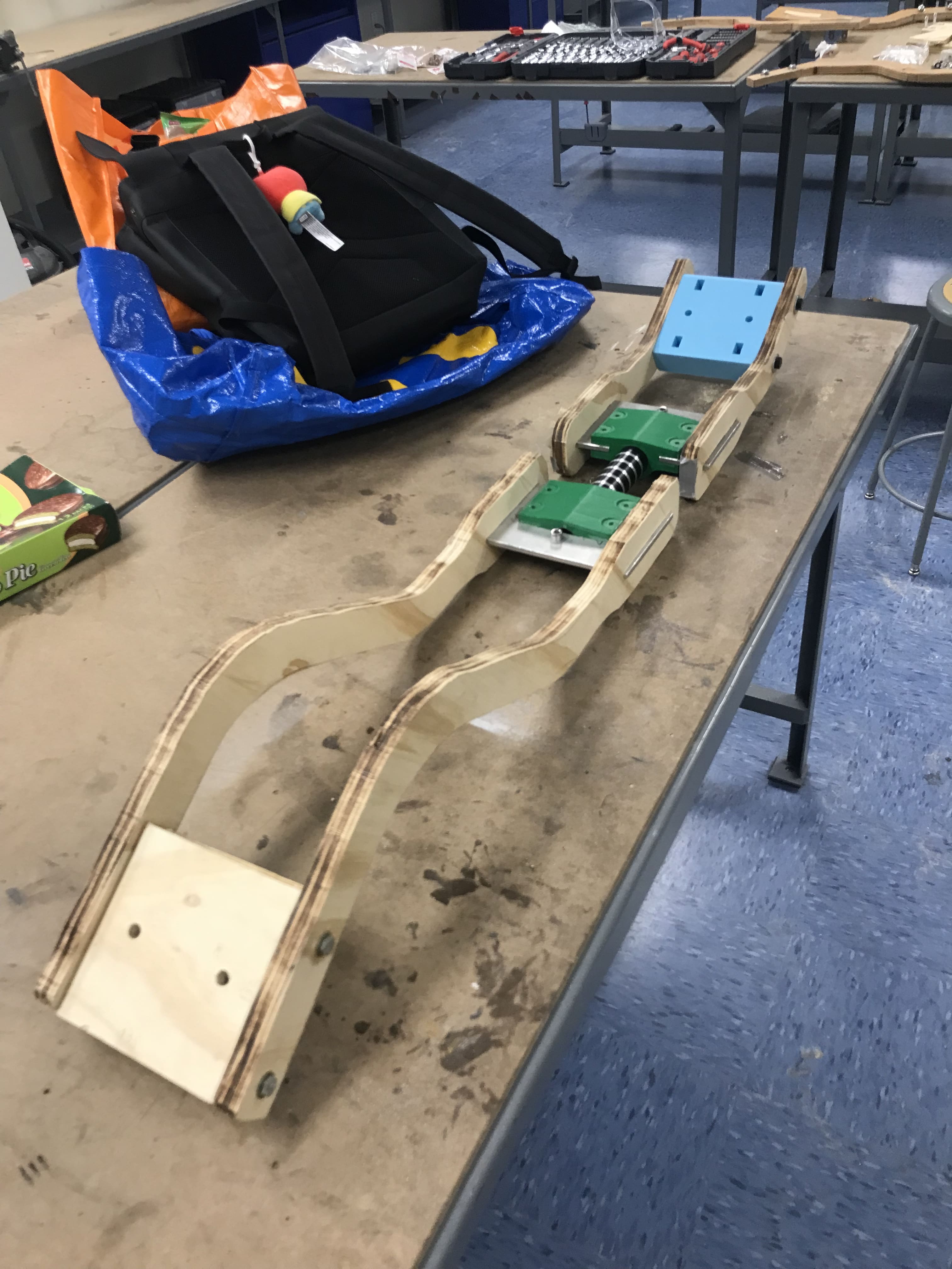
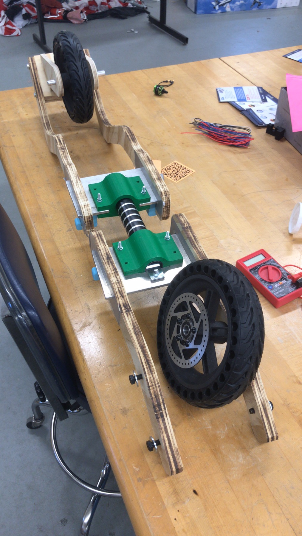
- (Continued) So, to have a lower standing elevation, I made the structure curve around the front wheel (you can check the pictures below). For the first prototype, the wheel didn’t turn 45 degrees when I was tilting the board. For the third prototype, even it was working for the scaled model, the wheel still didn’t turn as I expected (only about 25 degrees at the max tilt angle). It could be because of the large friction between the ground and the wheel or something else.
- (Continued) The conclusion is: what’s the dimension and the orientation of the caster that: (solving these problems simultaneously may solve the key of the kinematics that works for the caster board)
- the standing elevation can not be very high (ie using the scaled from the market product)
- let the wheel rotate 45 degrees when the board tilt angle is at the maximum (about 35 to 45 degrees)
- cause the board to rise some elevation at the instant of correcting the board to level when the wheel is still 40 to 45 degrees
- be able to reset the wheels to zero degrees (not even 2 or 3 degrees) just using human weight by simply standing on it (it might be related to both dimensions and friction). In past tests, it only went back to about 5 to 10 degrees no matter how I applied the vertical downforce on the board. (08/20/2023 Update: it’s very mass-sensitive. The center of mass has to be at the center)
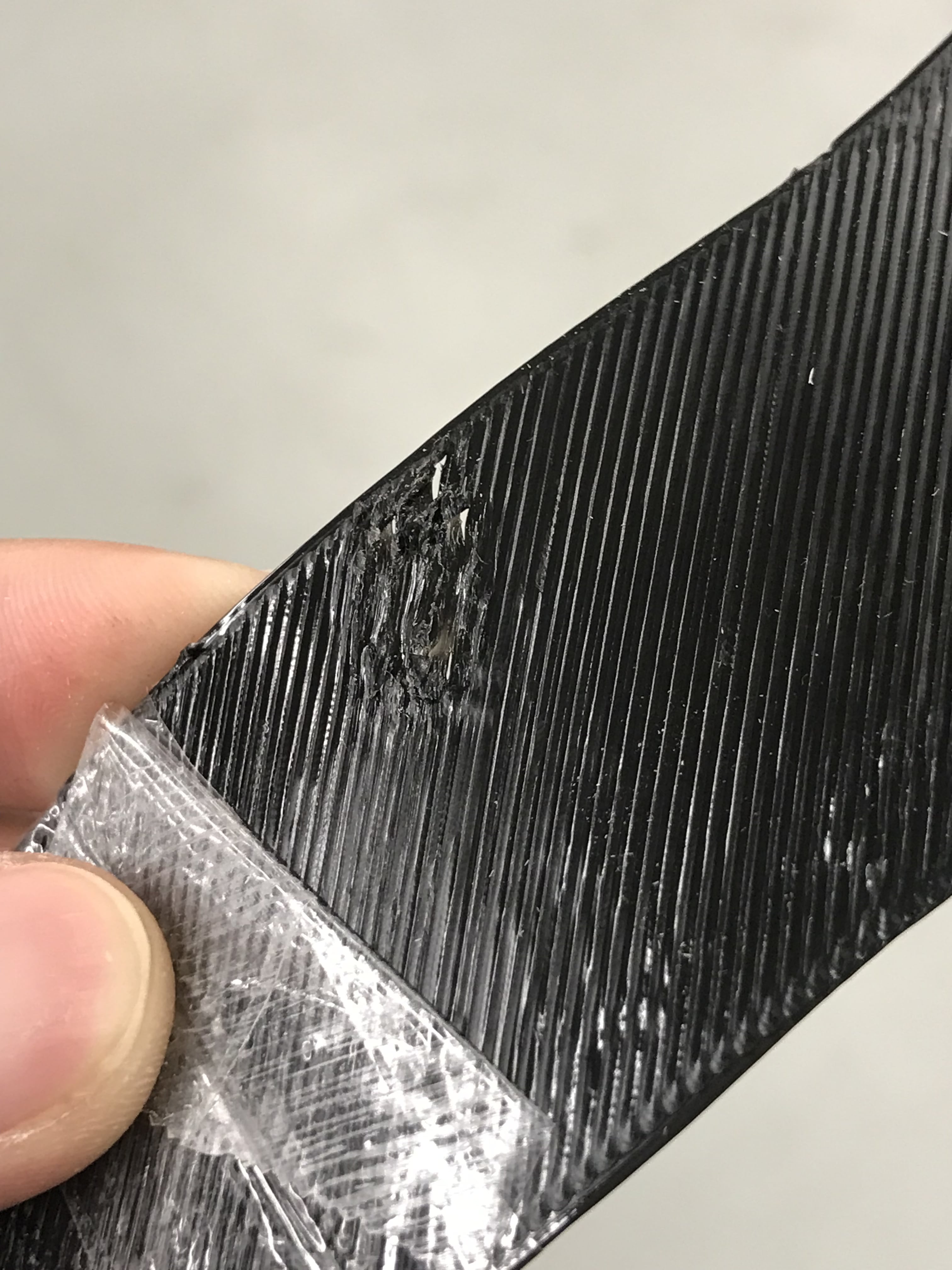
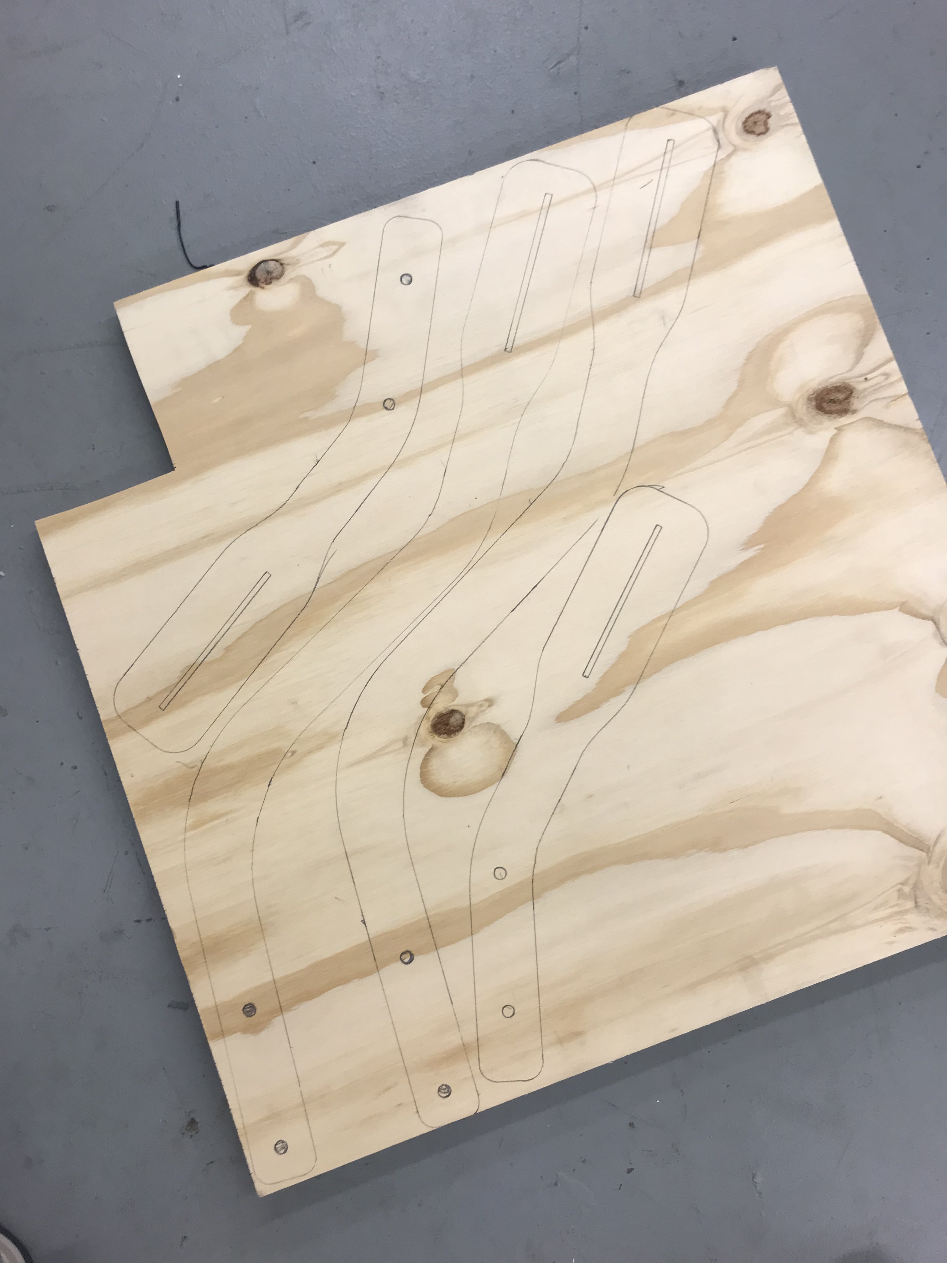
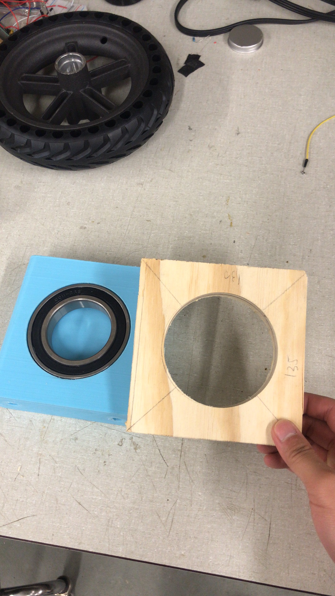
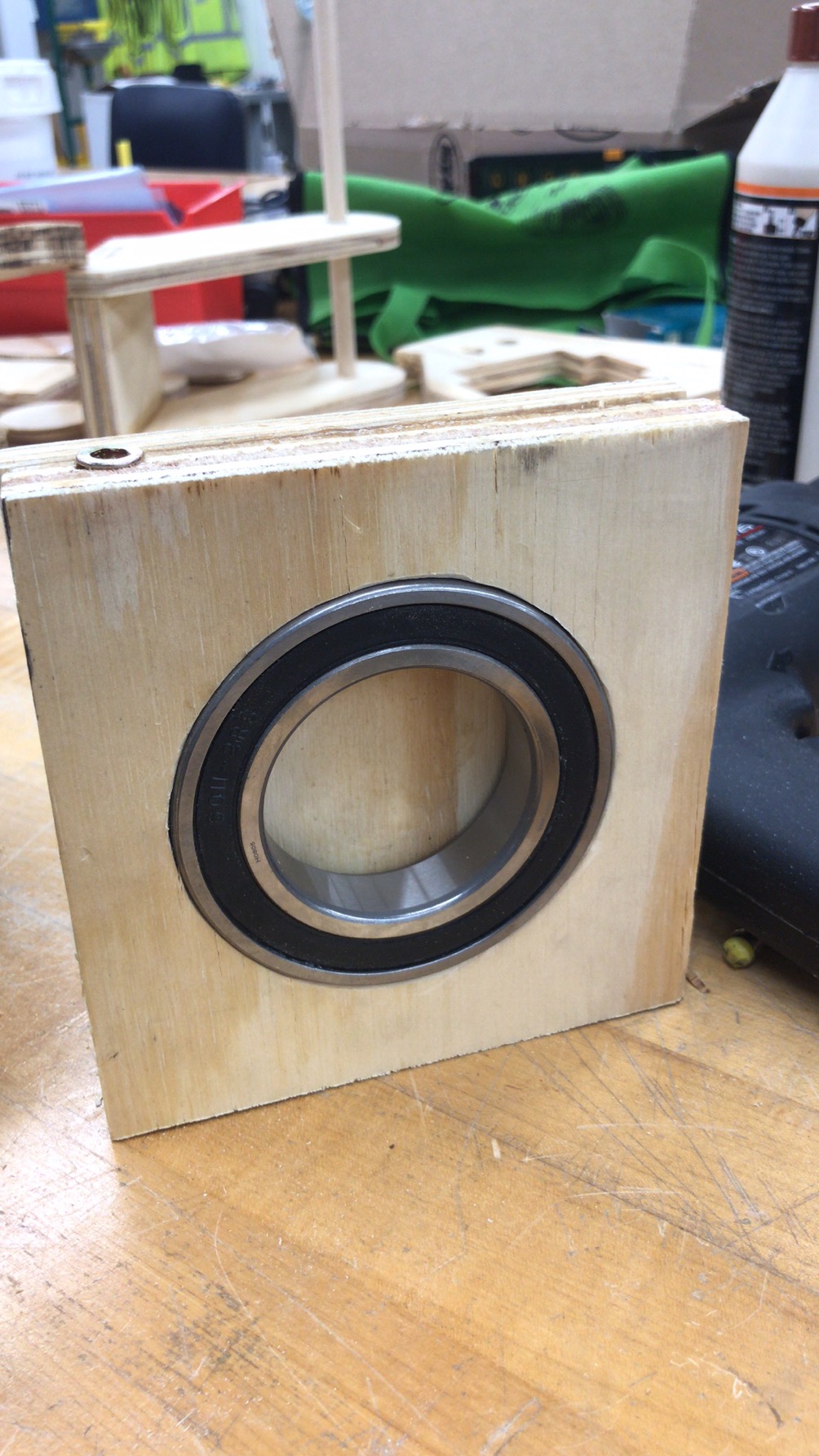
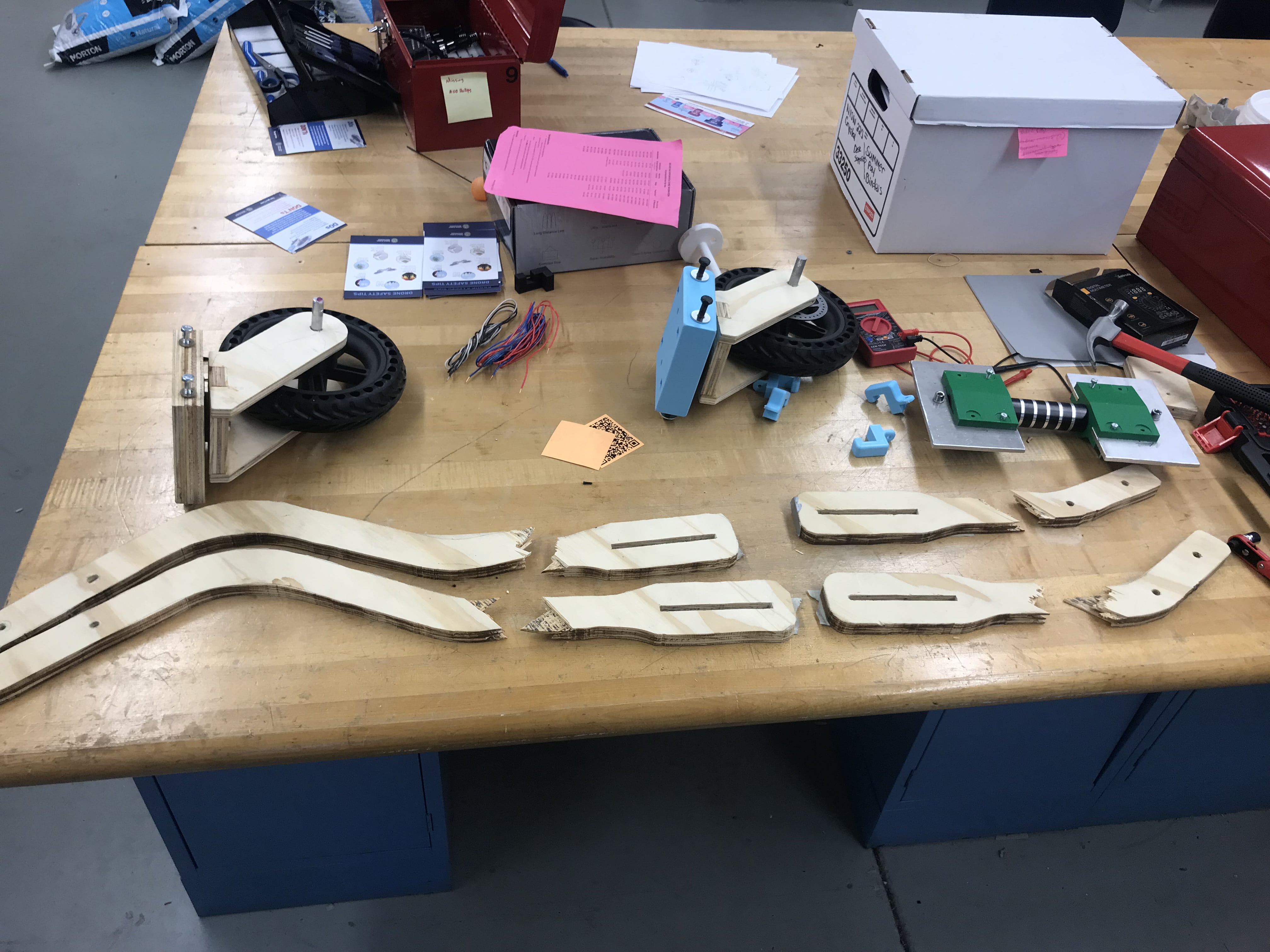
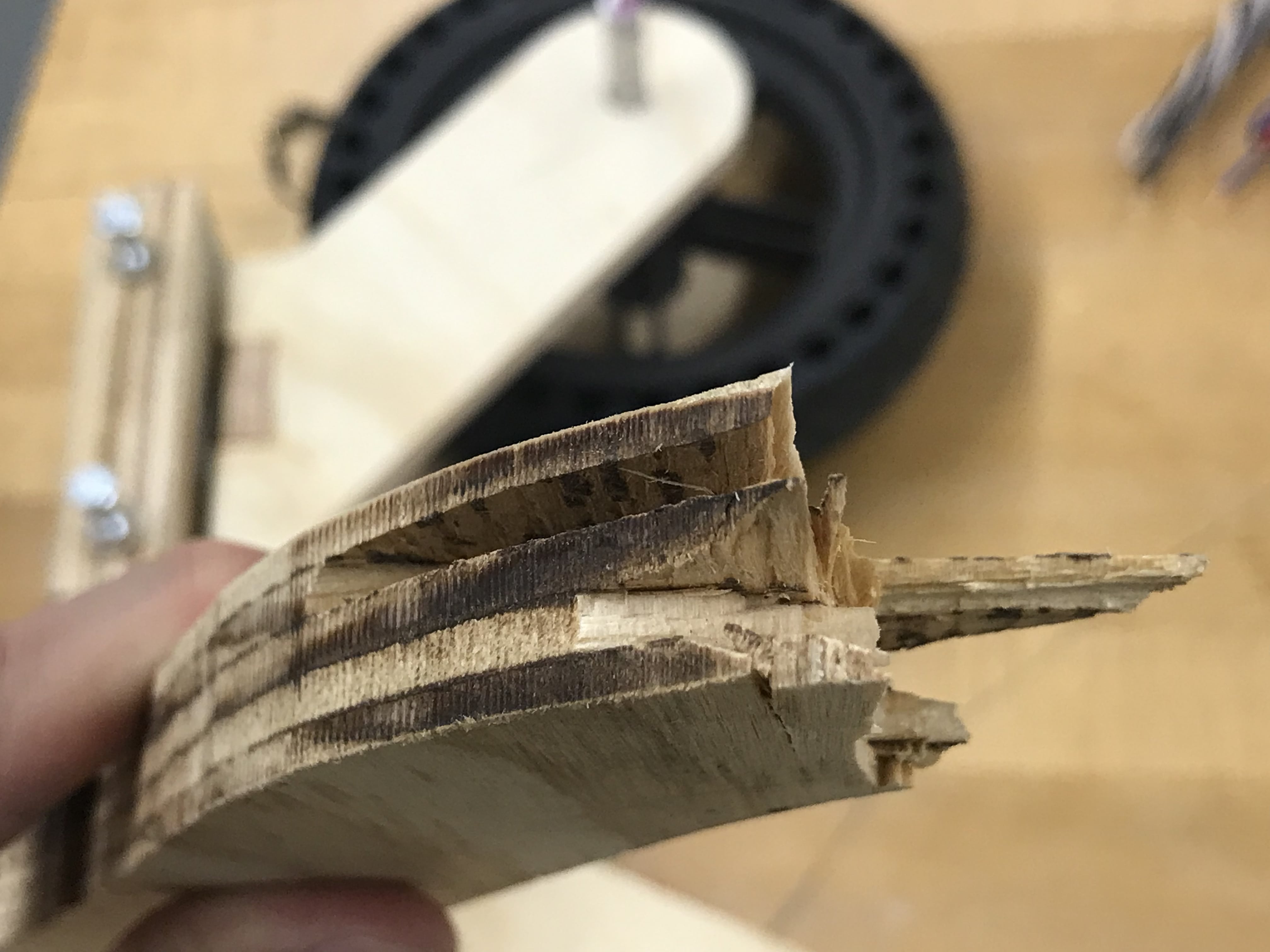
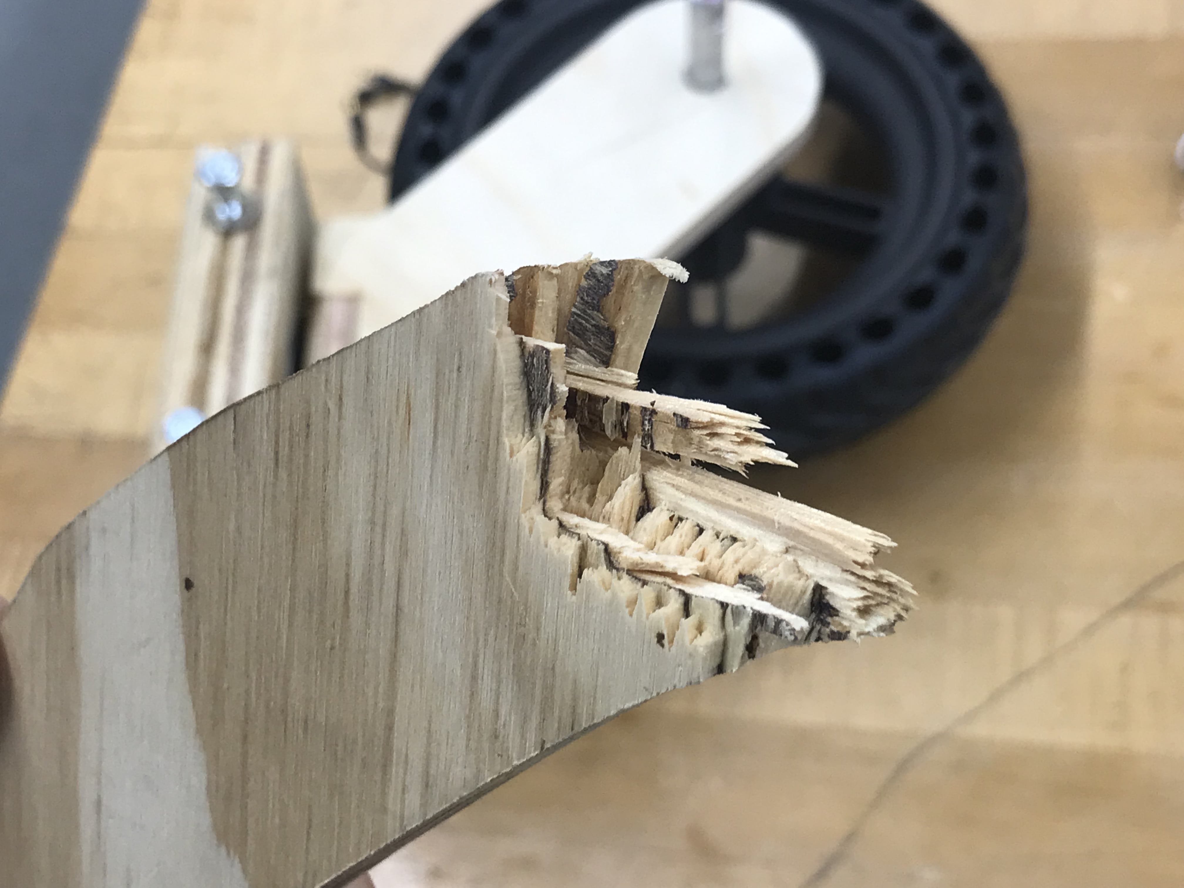
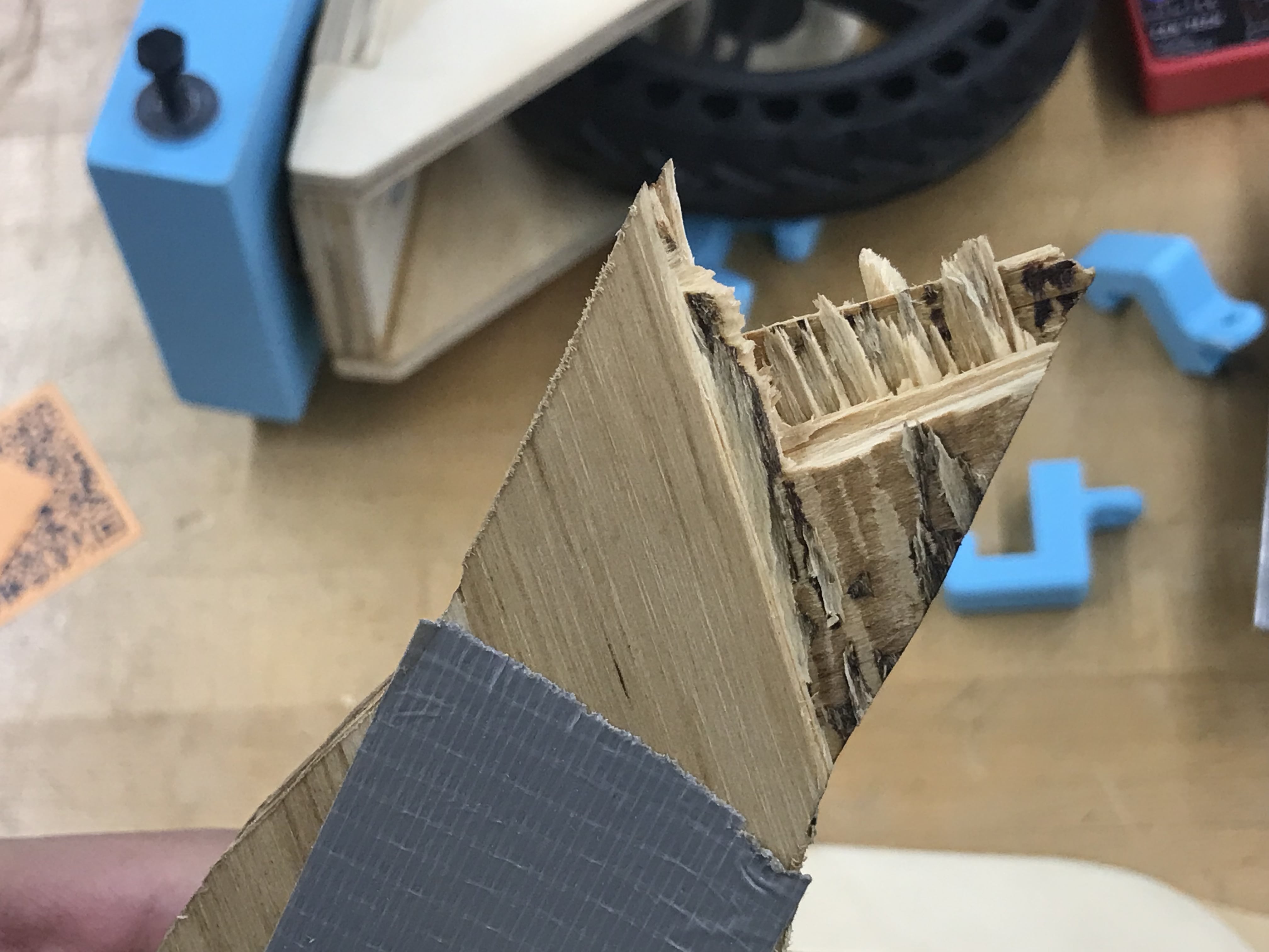
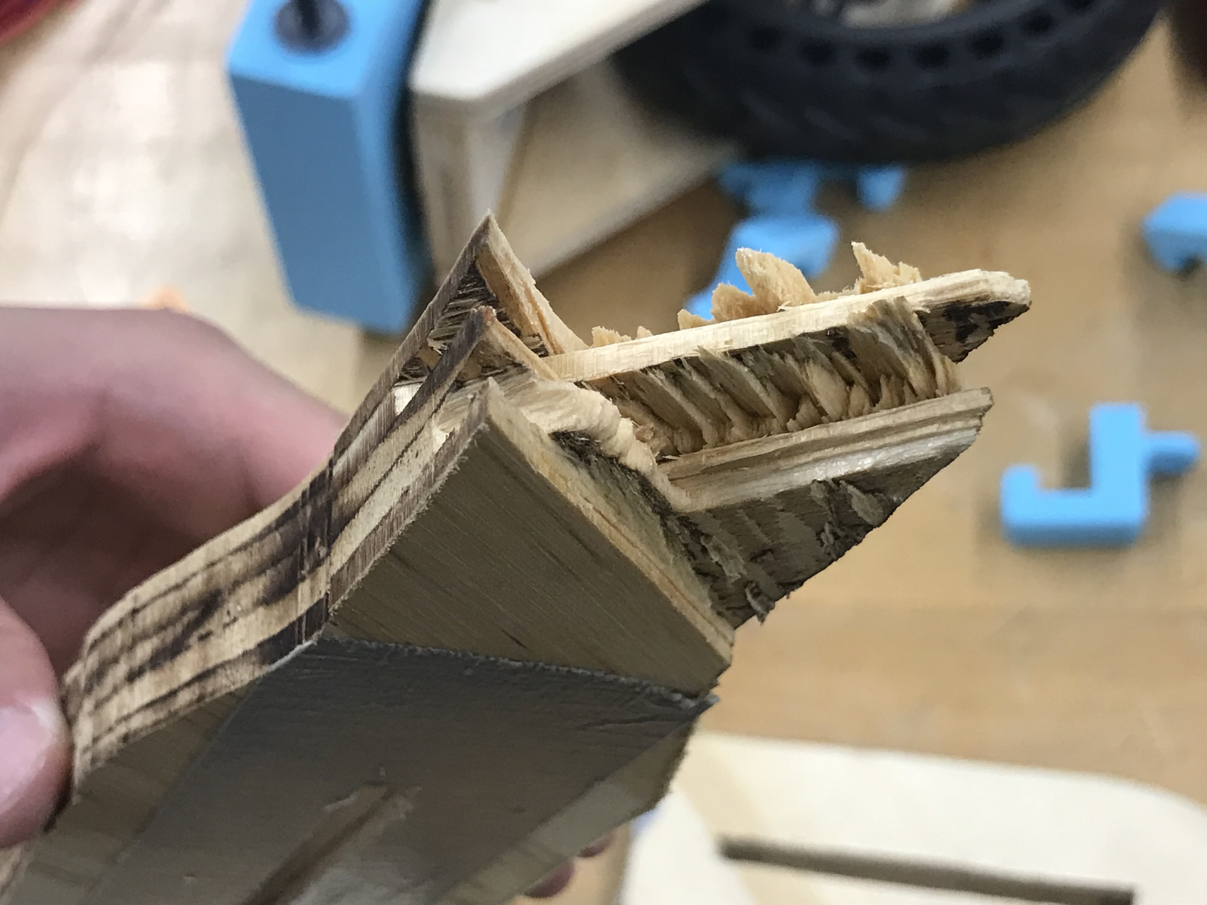
- Materials: the wheels were already very heavy because of the size and the aluminum hub. The two super large bearings are heavy. The torsion bar was not stiff enough. The plywood was not strong enough (the plywood I got for the second prototype failed weirdly, it might be because the direction of the load was perfectly perpendicular to the wood grain, and the glue was taking most of the load. See pictures in phase two). I am planning about the composite materials since plywood doesn’t work very well. I have learned a little about composite materials in MSE230 Structure and Properties of Materials during the 2023 summer, and I am also taking AT272 Intro to Composite Technology which I will be making stuff with composite materials. Hopefully, I can get started building new frames with carbon fiber and epoxy (I requested from ASME and they said it’s too expensive. Come on, man, they just said they still have plenty of funds that would be wasted if not used). Before that, I have to make sure the kinematics works.
II. Design Process
After the second prototype was done, I realized that I underestimated the complexity and difficulty. More careful benchmarking, more calculations, and small-scale prototypes should have been done.
A. Goal
Design and build a casterboard that can overcome the complex campus terrain, mainly for the gaps that are larger than 5 mm.
B. Concept Flow
The first decision was to use bigger wheels. If we know the wheel diameter and the gap size, we can calculate the amount of elevation descended by using simple trigonometry and Pythagorean theorem.
D: diameter in inches
R=D/2; radius in inches
d: gap width in cm
y: elevation descended in cm
Equation editor: \frac{y}{2.54} = \frac{D}{2} - \sqrt{ \frac{ D^{2} }{4} -\big( \frac{d}{2 \times 2.54} \big) ^{2} } 
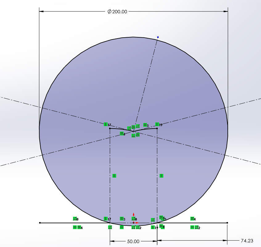
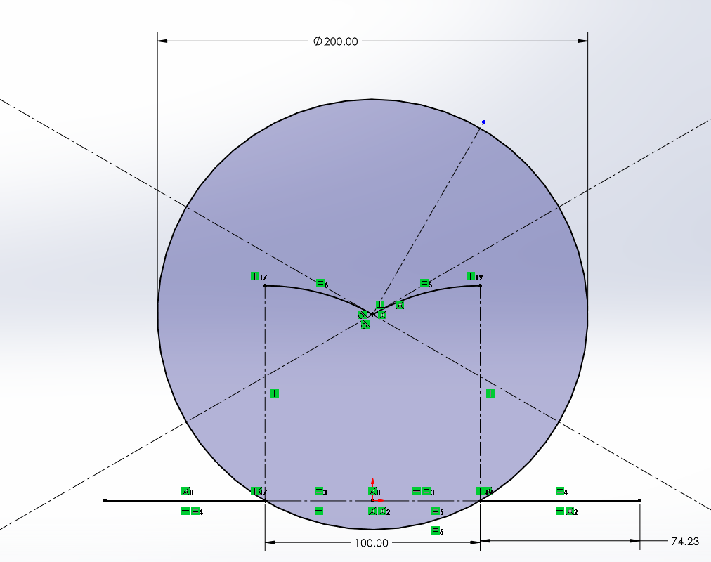
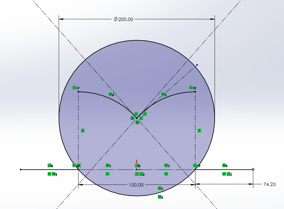
However, the elevation is not the critical element that determines if the wheel can pass the gap or not. If I draw a sketch and apply the geometric constraints, we can clearly see the path that the center of the wheel is going to follow, which the center of the wheel has the same path as the standing board, that is, this path will have a direct feedback to the rider. The following drawing is based on these assumptions: no slipping, ignore the wheel deformation, the wheel is touching to the ground all the time, the moving direction of the wheel is perpendicular to the gap, and the gap is infinitely deep.
- Line l: the construction line from upper left to lower right.
- Line m: the construction line from lower left to upper right.
- Line p: the construction line that is perpendicular to line l.
- Two arcs at the center: the path of the center of the wheel. Each is tangent to line l or line m.
- Angle of Incident (AOI): the angle between line p and line m.
In the first three pictures, the gap width (d) is constant, and I am changing the wheel size. See how the AOI changes:
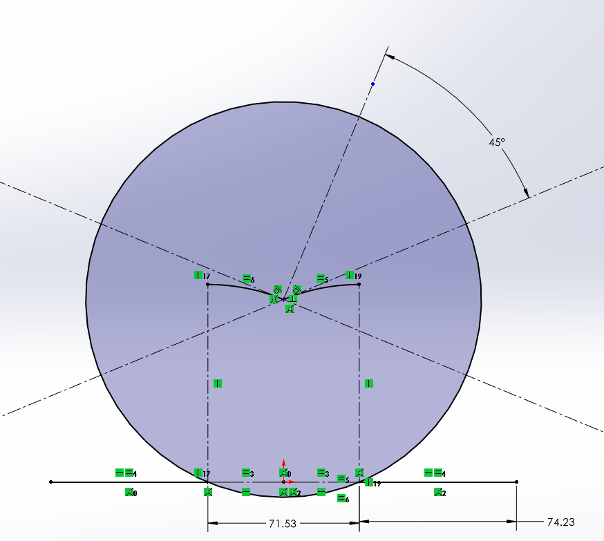
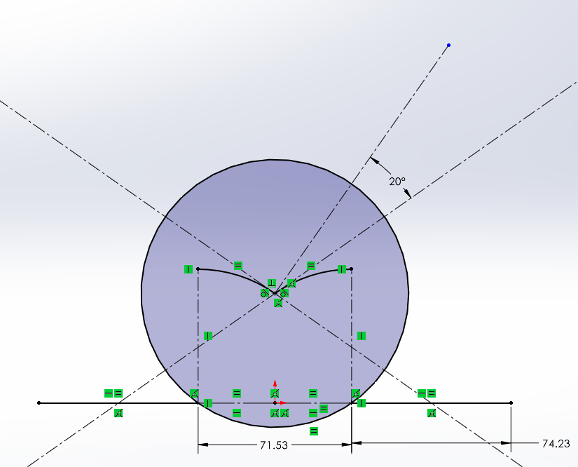
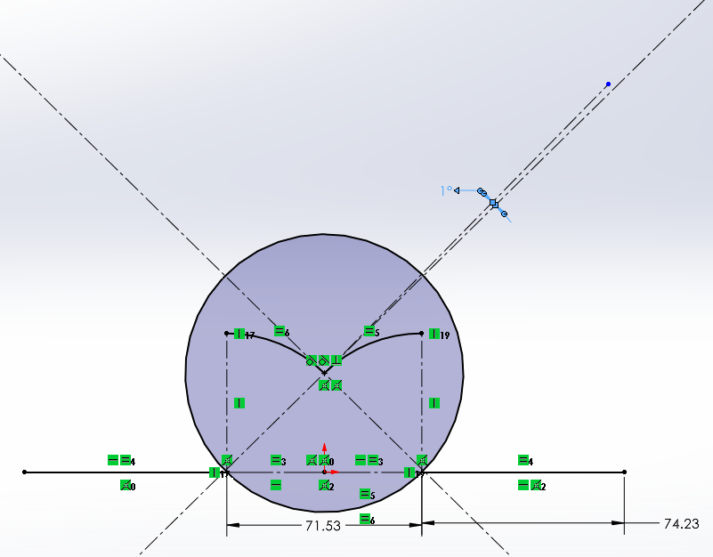
As the wheel size is getting smaller, AOI is getting smaller (45 -> 20 -> 1).
Now if I set the wheel size to be fixed and just change the gap width.
The AOI can be found in the following steps:
- Find the equation of the circle (the path), where the center of the circle and the coordiante is at the edge of the gap, and the radius is the radius of the wheel.
- manipulate the equation so elevation y=f(R, d).
- Find the derivative and the slope at d/2 or -d/2, depending on which line you are working with.
- Use arctan to find the angle of line m and line l.
- Use perpendicular relation to find the AOI.
Since line m and line l are symmetric to the horizontal, we can have the equation AOI=f(R, d).
AOI=90^{o} -2*atan( \frac{d}{\sqrt{4 R^{2}- d^{2} } } )
Using linear momentum and AOI, we can see larger AOI will have larger linear momentum in the direction of the path after the wheel reaching the lowest point, therefore easier to pass the gap.
Finally, an 8.5” wheel is chosen. A larger wheel could be over-designed and harder to control.
Then, if I scale up (comparing with the market product, wheel=3”), lowering down the standing board, and let the front board to curve above the front wheel. The tilt angle of the caster base is maintained at 30 degrees below the horizontal.
But for the first prototype, I didn’t really scaled it up because I was using the commercial caster I found online. Based on that caster, I determined the height of the standing platform and all other dimensions.
III. First Prototype
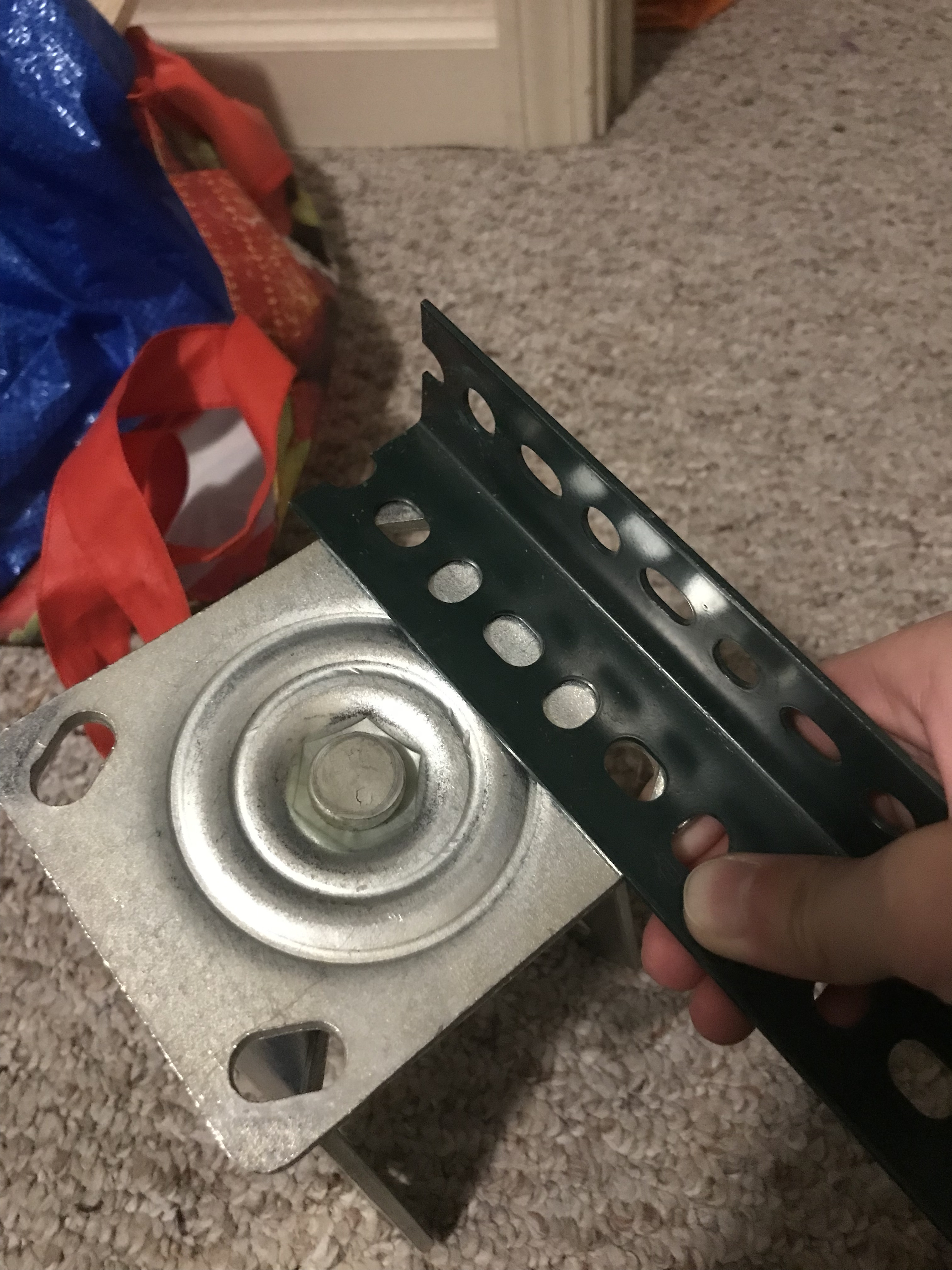
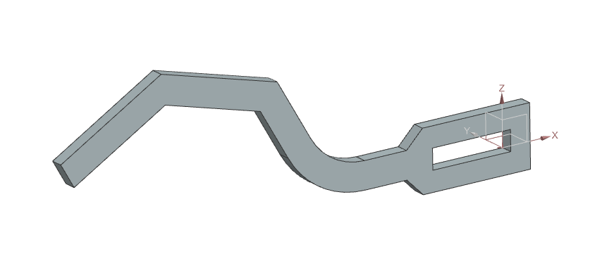
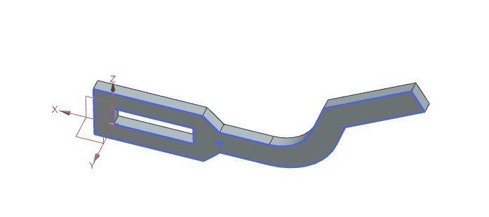
This table shows the theoretical maximum stress it will experience
| Item | Equation | Value |
| Weight (N) | W=mg/4=85*9.81/4 | 208.46 |
| Moment (N-m) | M=Wl=208.46*0.407 | 84.84 |
| Second moment of area (m^4) | I=1/12*bh^3=1/12*0.0254*0.04^3 | 1.355E-7 |
| Max stress (MPa) | Bending stress=My/I=84.84*0.02/(1.35E-7)*10E-6 | 12.5 |
| Factor of Safety | FS=failure stress/stress=27.6(?)/12.5 | 2.2 |
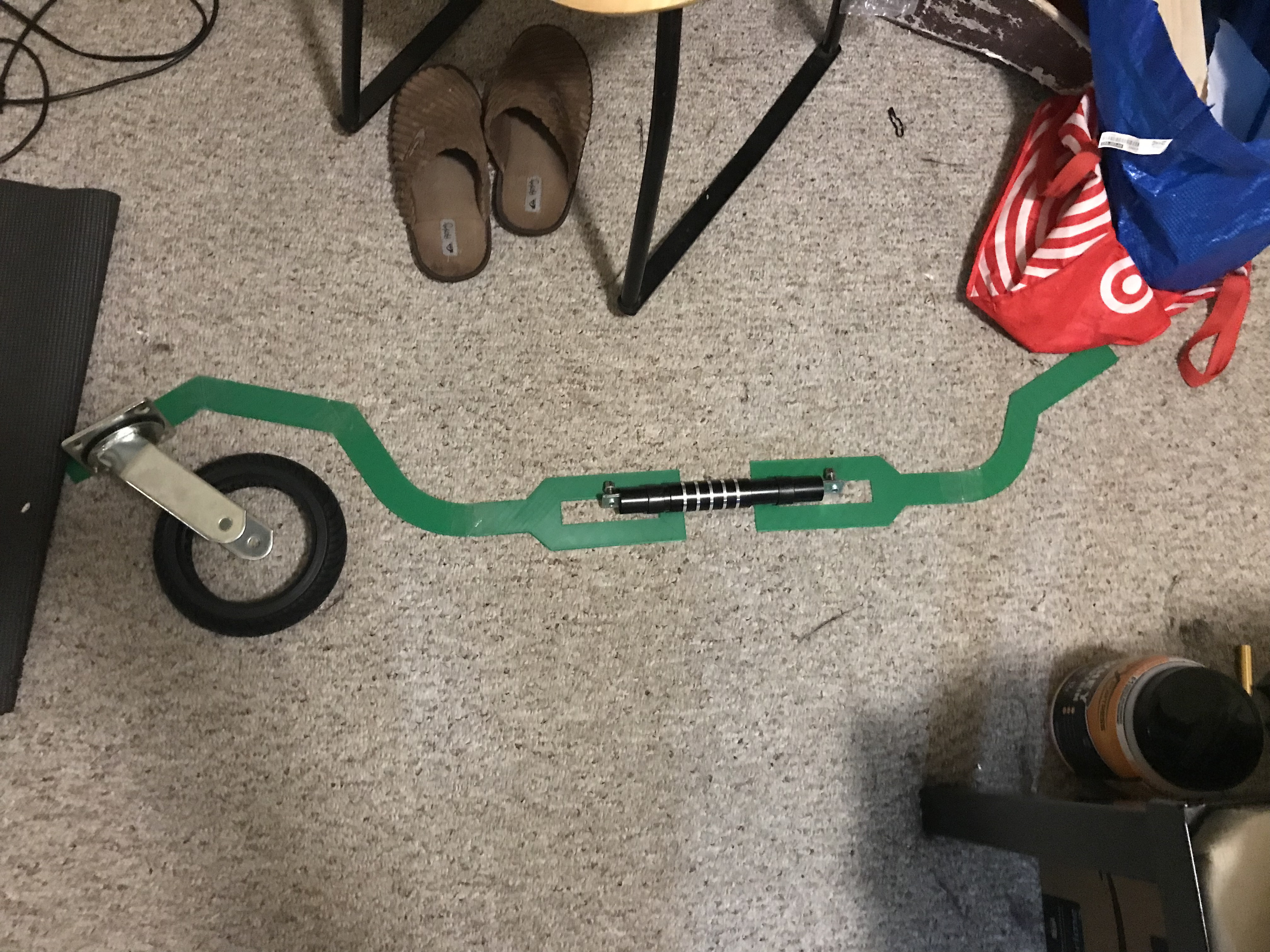
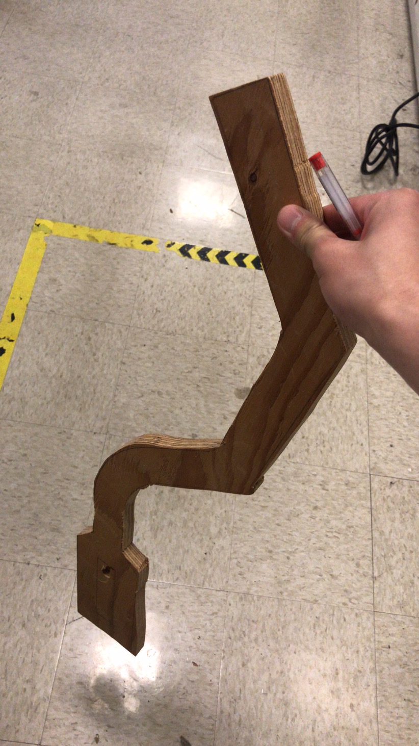
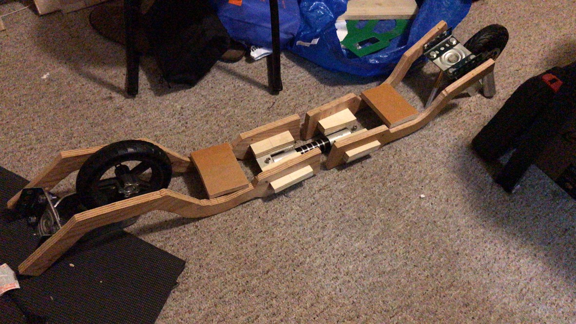
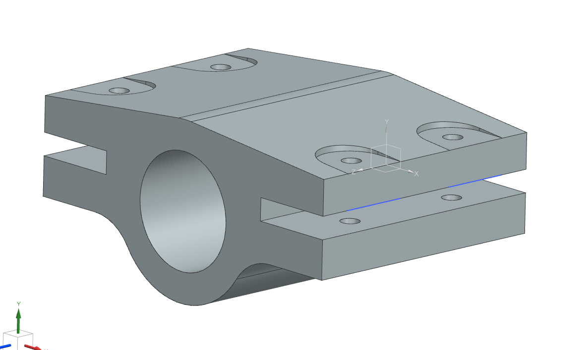
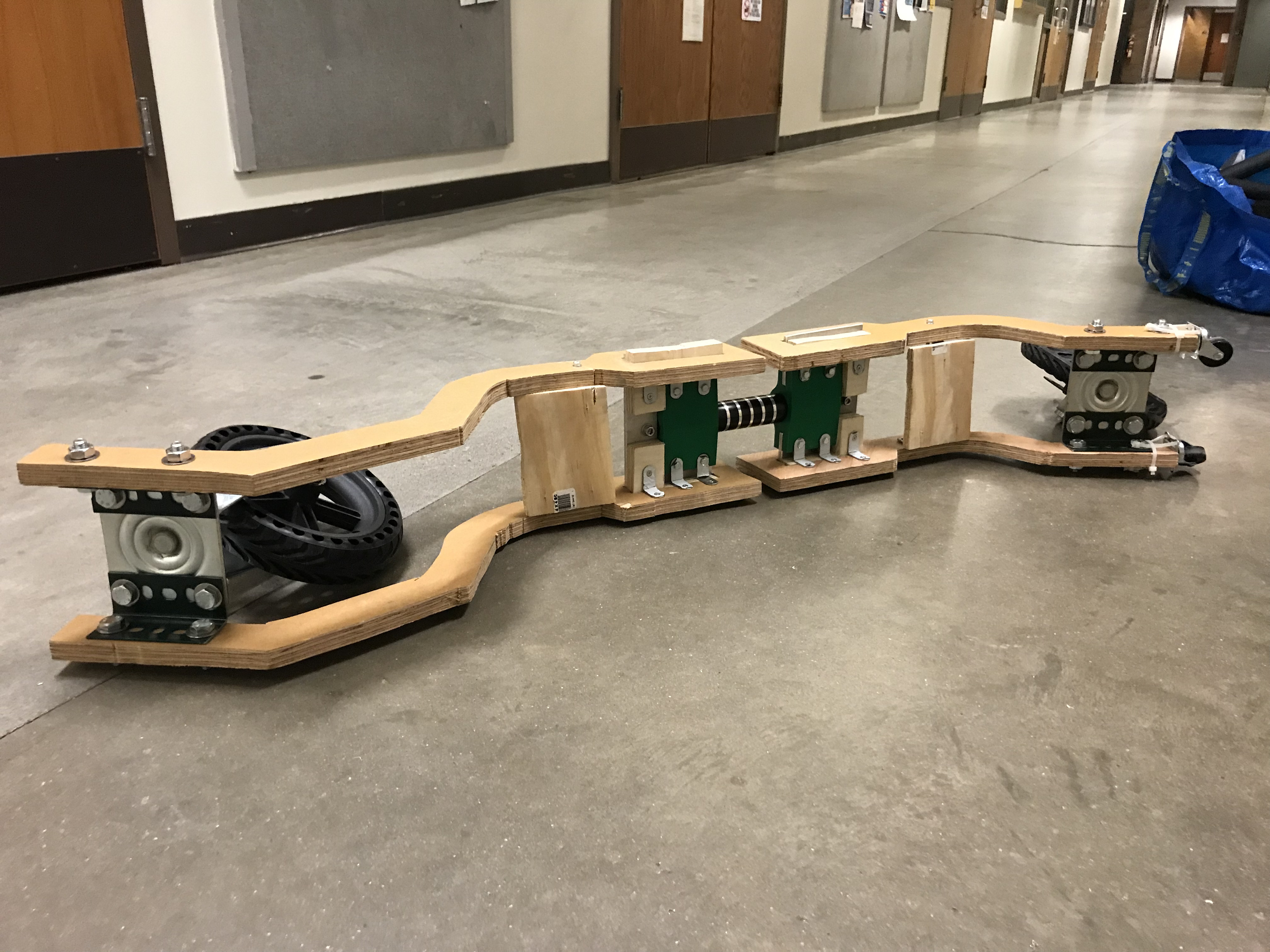
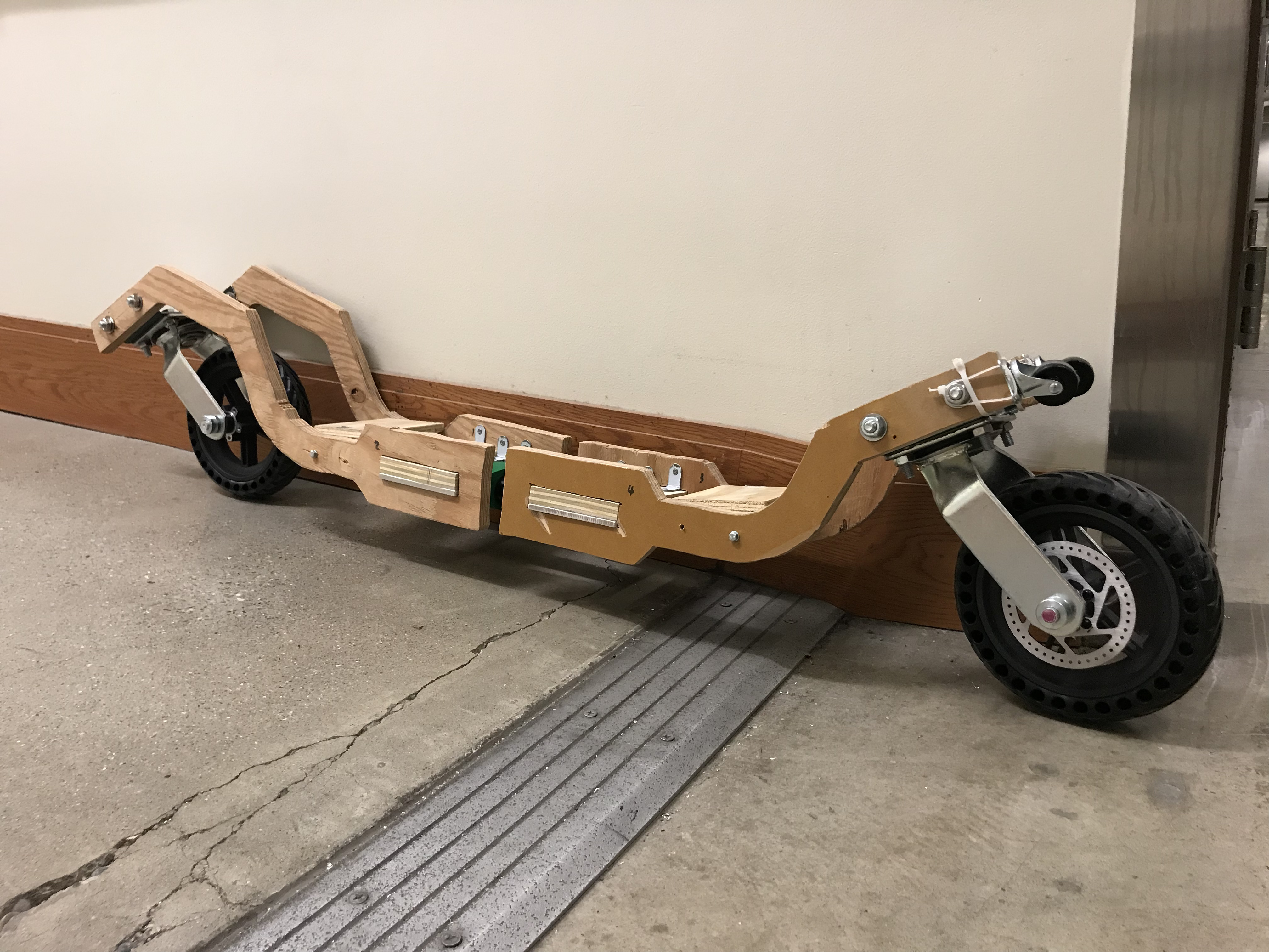
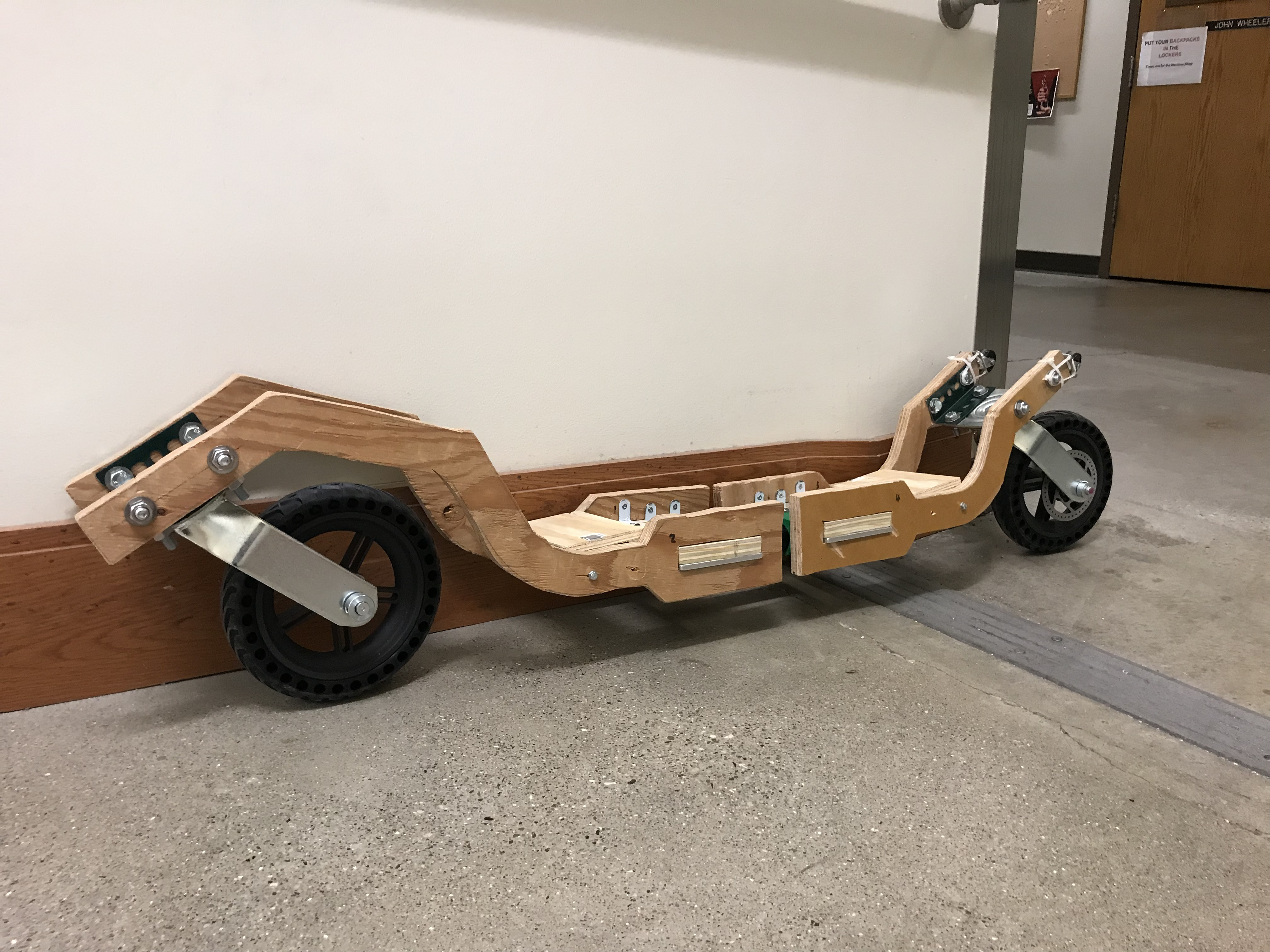
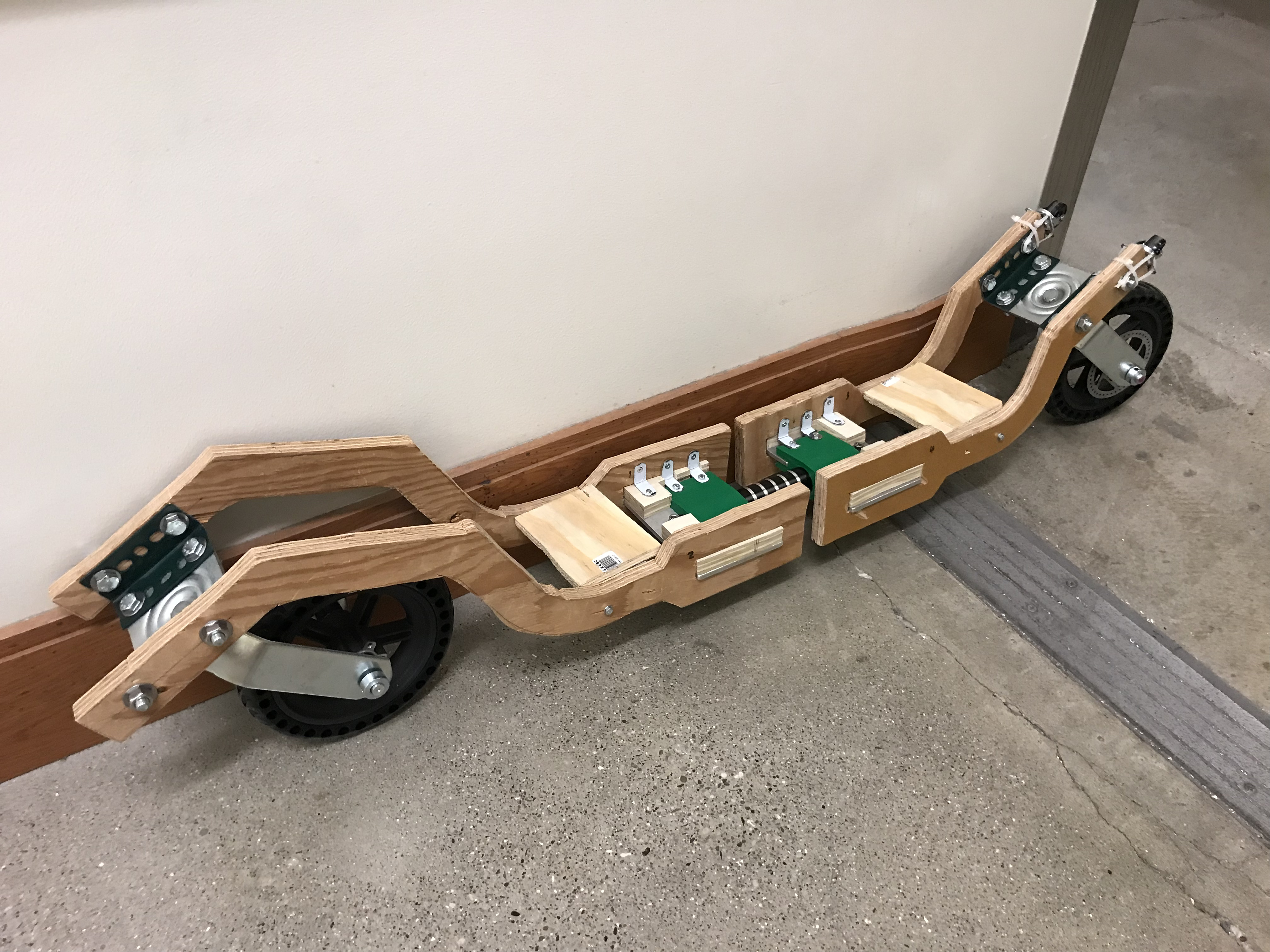
It supported my weight with no problem at all. From the surface inspection, no permanent deformation or over-compressing occurs. It’s in the factor of safety as expected.
Reasons that it’s not ridable:
- Too heavy, about 11 kg.
- Bad casters:
- Each caster is about 3 kg.
- Bad lubrication inside.
- Incorrect dimension causing incorrect kinematics.
- CG of the wheel is not centered with the caster fork.
- The lower face of the standing board is too close to the ground.
IV. Second Prototype
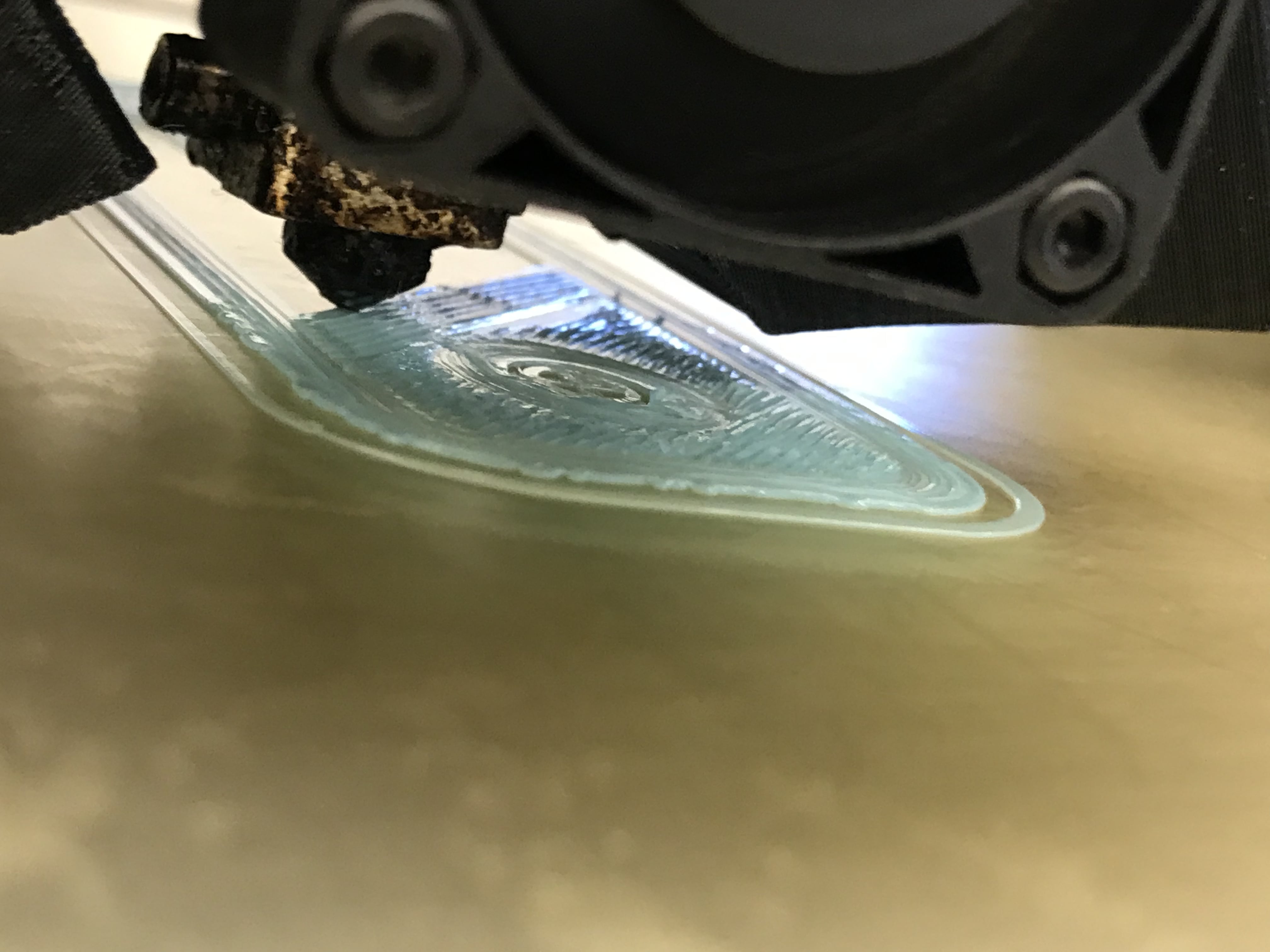
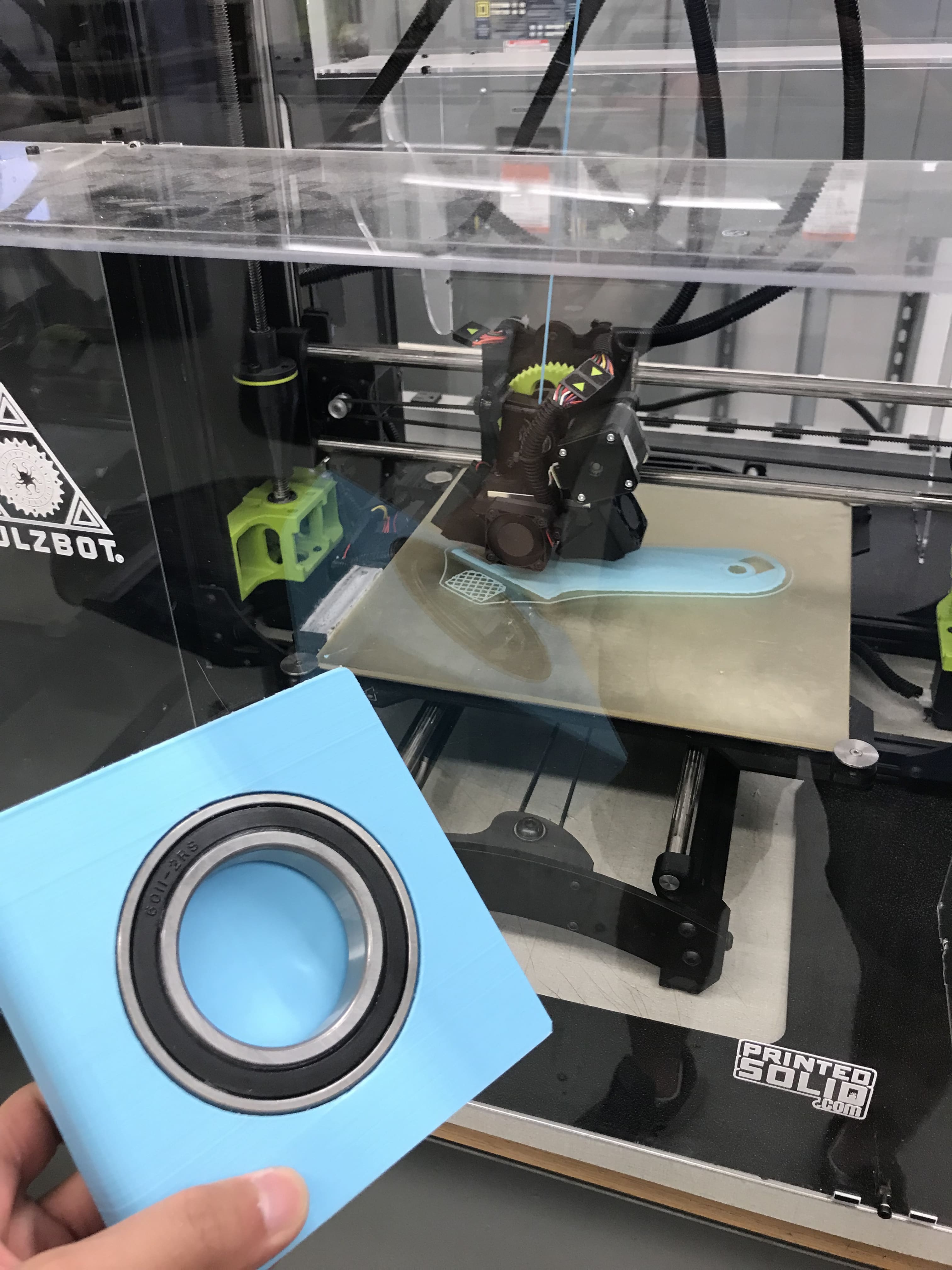
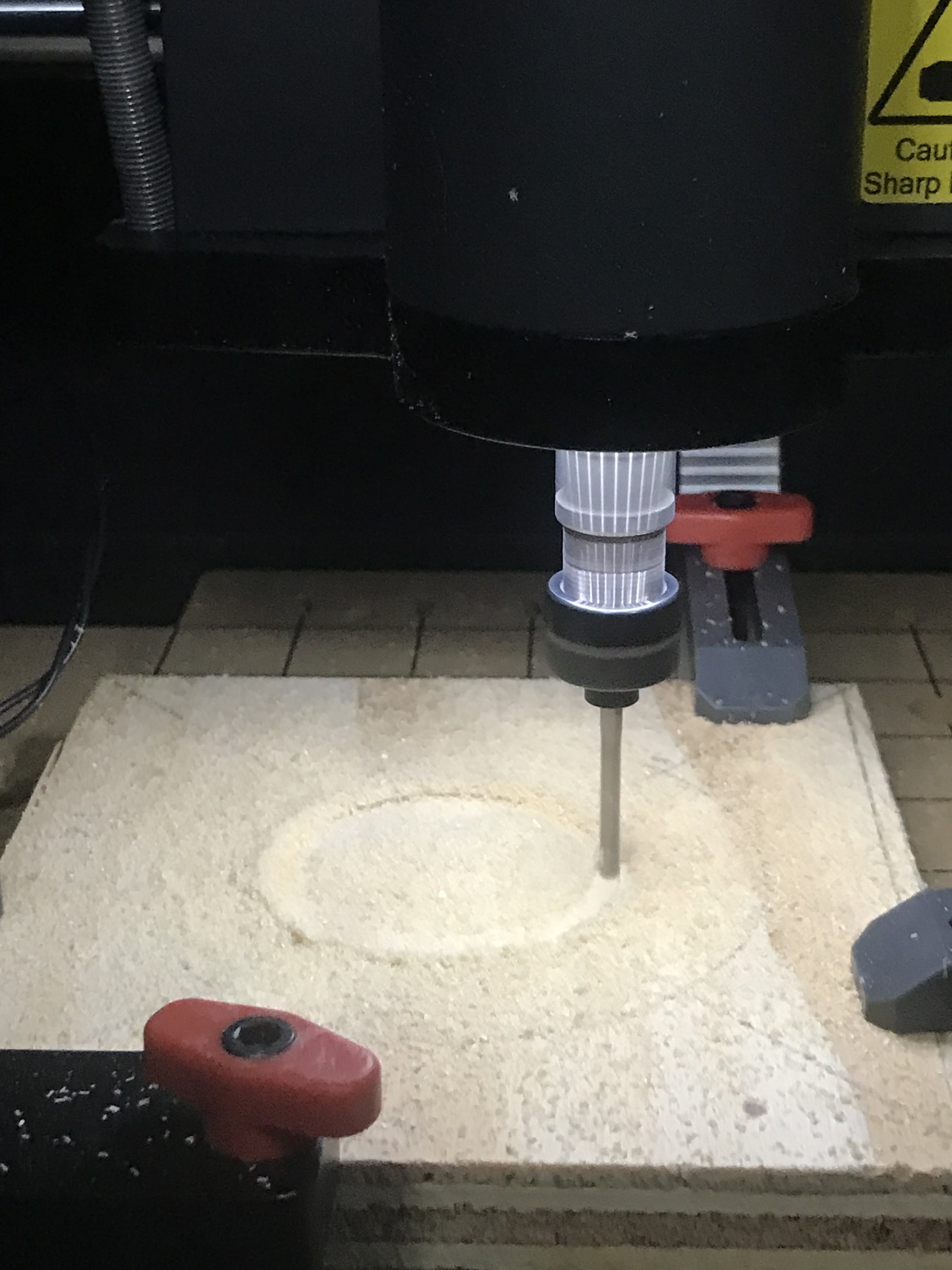
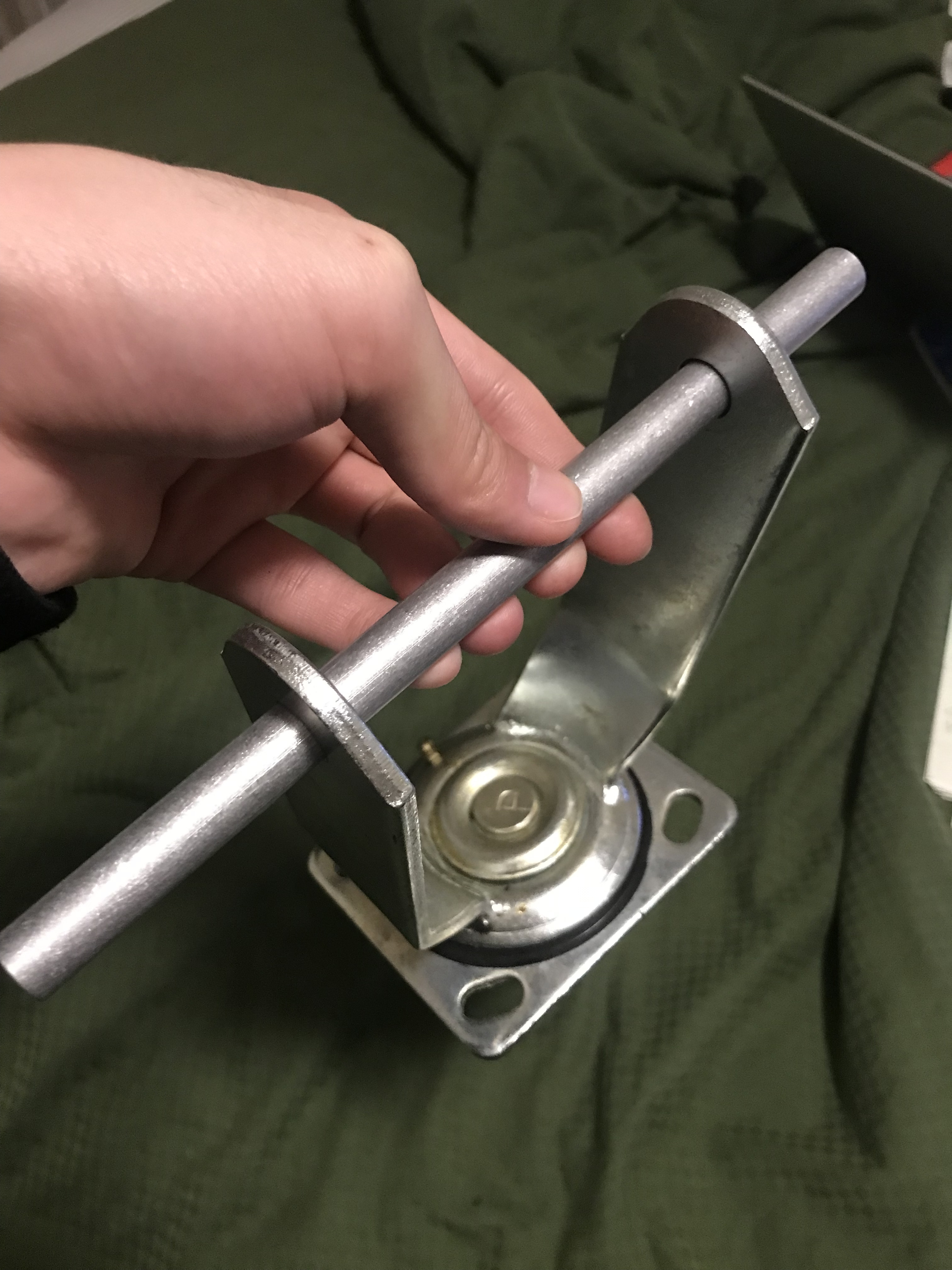
This time, I decided to build the caster by myself. So I measured the caster of the marketing product and scaled it up. I found that the wheel is tangent to the rotation axis of the caster fork.
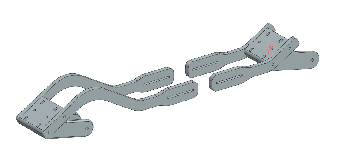
| Item | Equation | Value |
| Weight (N) | W=mg/4=85*9.81/4 | 208.46 |
| Moment (N-m) | M=Wl=208.46*0.446 | 92.97 |
| Second moment of area (m^4) | I=1/12*bh^3=1/12*0.0254*0.04^3 | 1.355E-7 |
| Max stress (MPa) | Bending stress=My/I=92.97*0.02/(1.35E-7)*10E-6 | 13.7 |
| Factor of Safety | FS=failure stress/stress=27.6(?)/13.7 | 2 |
