Content:
0. 1 vs 3 Battle Replay
- Hardware
- Suspension System
- Mecanum wheel
- Hex Coupling
- Spiral Spring
- Chassis
- The Weapon Flipper: Two Designs
- Dynamic and Kinematic Analysis in Creo
- Armors
- Front Armor
- Side and Back Armor
- Top Armor
- Suspension System
- Electronics
- Motors, servos, ESP32, battery, jump wires, and solderable beadboard
- Pololu Adjustable 4-12V Step-Up/Step-Down Voltage Regulator S18V20ALV
- Matek Systems UBEC DUO, 4A/5~12V & 4A/5V
- Voltage Monitor
- Wiring
- Controls
- Bluetooth Serial Communication Setup
- Improvement of joystick on a smooth surface
- Code
- Test Drives
- The Final Battle
- Performance Analysis
- Damage on Armor
- Reflection
- Suspension
- Mecanum wheels
- Flipper
1 VS 3 Battle!
Update in October 2024: I won both 1 vs 3 battles. Here are the battle replays. Other robots have 2s 1500mAh 15C Li-Po batteries without over-current protection and low voltage protection, I have two 2s 700mAh Li-ion batteries with both protections in series, but I have low latency Bluetooth control.
The blue robot has a low wedge that is super close to the ground. It can scoop robots easily and let them lose traction, except mine. Mine wedge is pushing against the ground. Theirs still has a half-millimeter to one-millimeter gap, and the front gap becomes larger when it’s accelerating forward.
Intro
Date: Jan. – Feb. 2024
Battle has no motor limitation! And one extra battery!
Spec:
- Length: 246 mm
- Width: 250 mm
- Height (suspension unlock/lock): 88.4 mm / 98.7 mm
- Mass: 1890 g
- Running Time (1/2 batteries): 8 min / 20 min
1. Hardware
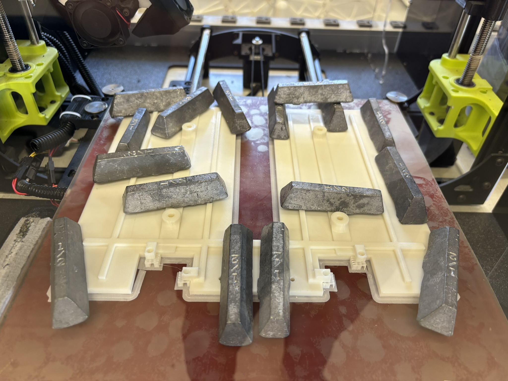
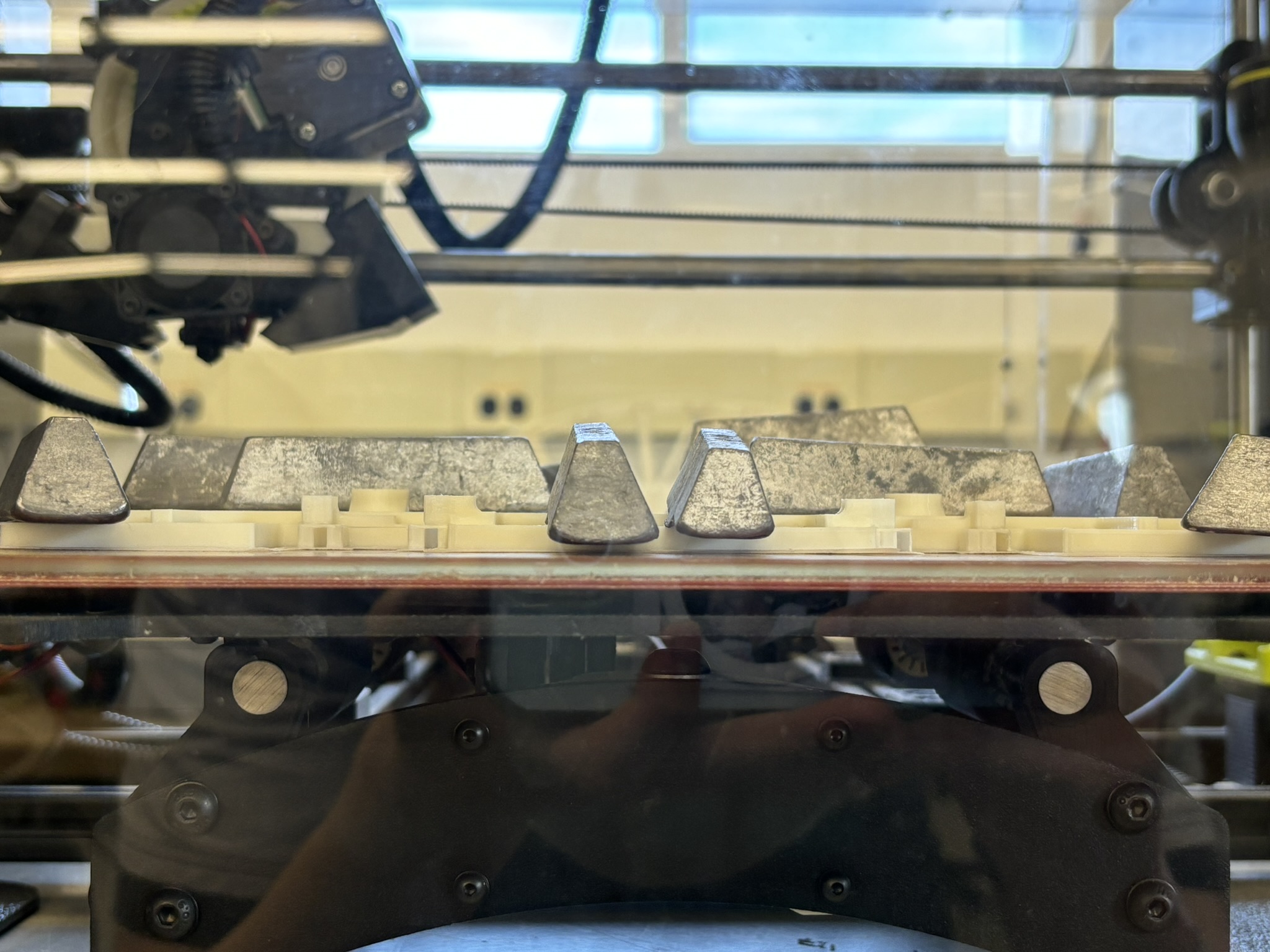
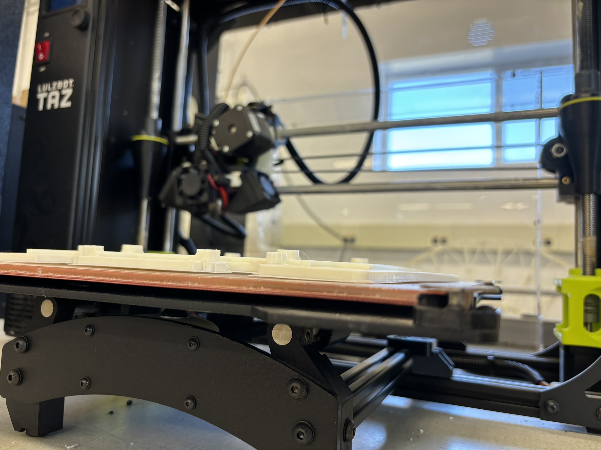
All 3D printing parts are PETG, which has a much better toughness than PLA but with similar density. But unlike PLA (300 mm/s on outer wall with 124% speed up), it prints much slower on my printer (200 mm/s without speed up).
1.1. Suspension
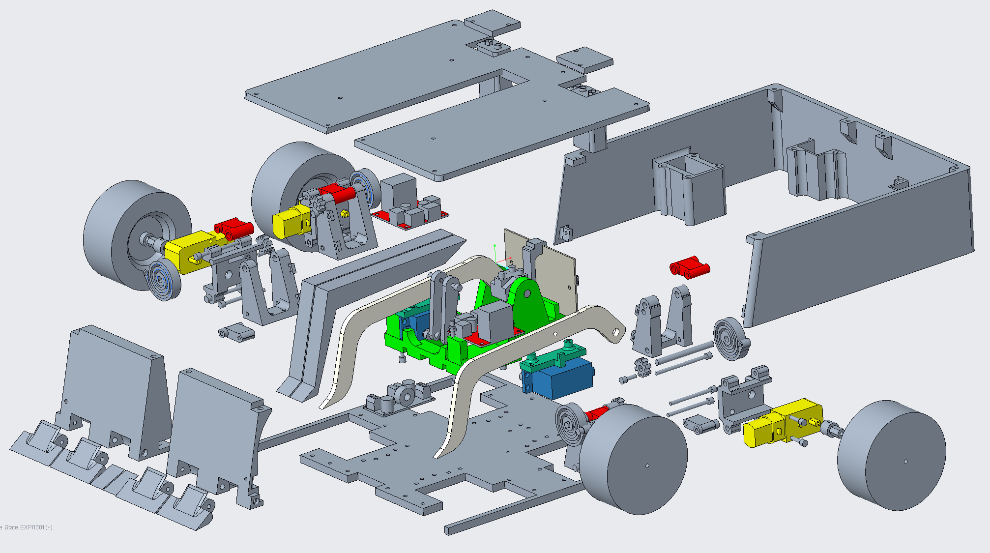
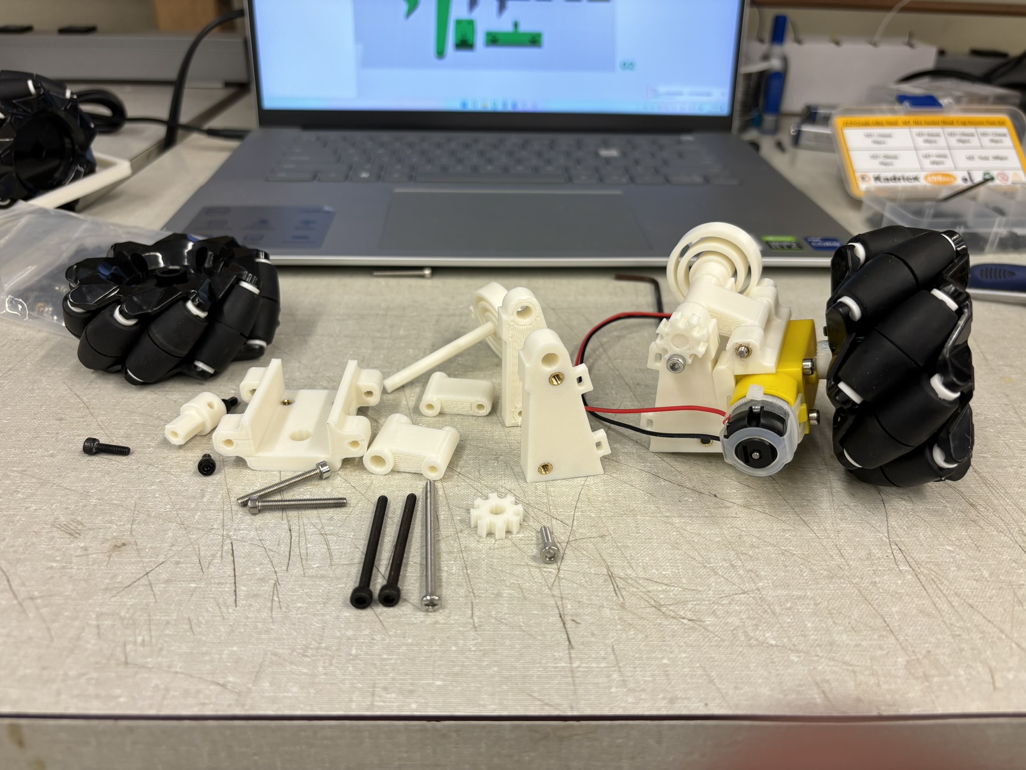
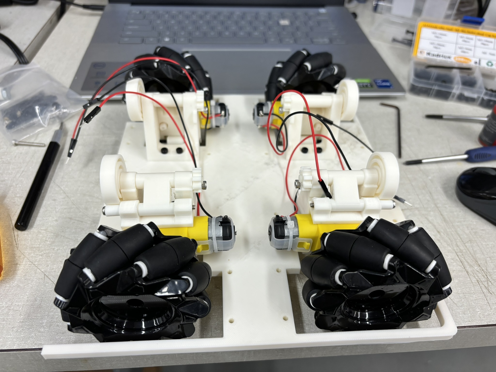
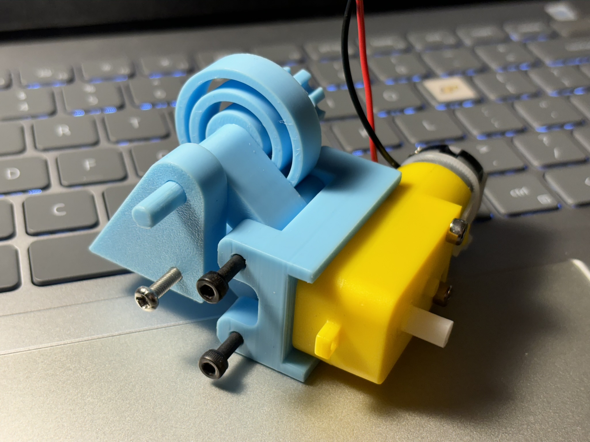
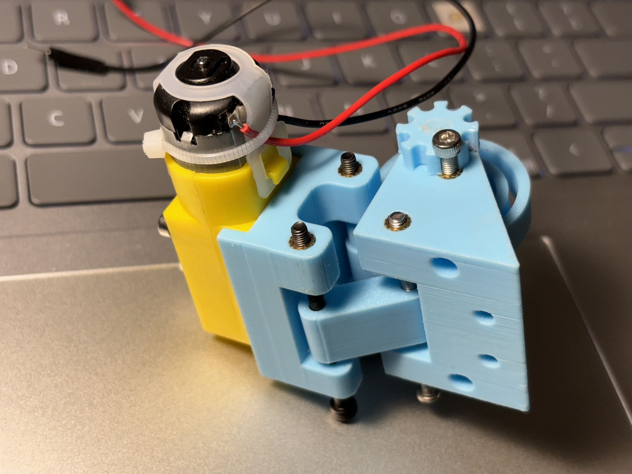
The main purpose of suspension is to make sure all four wheels are touching the ground. The suspension has the limit stop so the chassis won’t touch the ground when pushed down and two loops for zip ties for wiring organization.
1.1.1. Mecanum wheel
Mecanum wheels allow the robot to run in all direction (pitch, roll, yaw). With proper algorithm, it can go side ways (See test drive videos). This specific Mecanum wheel has a really soft rubber and provides really good grip on any surfaces.
1.1.2. Hex Coupling
Hex Coupling connect the gear box output shaft and the wheel. It’s experiencing random torsion load and cyclic bending load, so the orientation of printing is very important. All four of them broke after a short test drive without the armor and weapon, and that’s no good. Even though PETG has a better layer adhesion than PLA has, it still break. So I change the orientation of printing to 45 degrees, and they are too good to break. I am not sure if the thread locker is also expanding the layer adhesion.
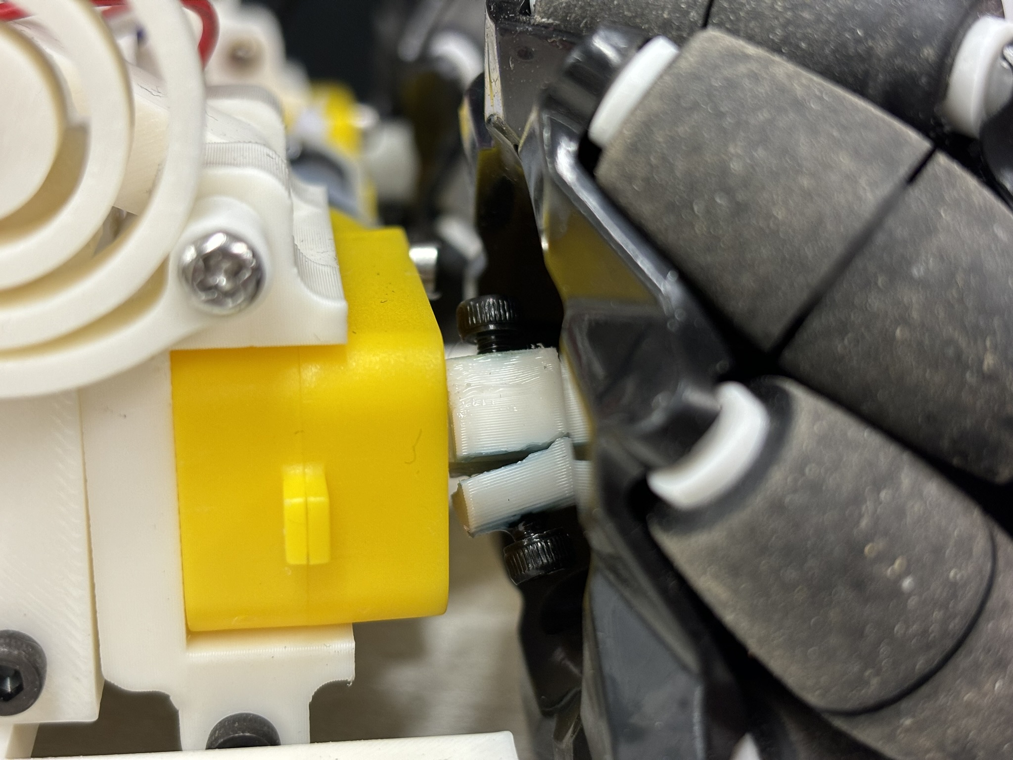
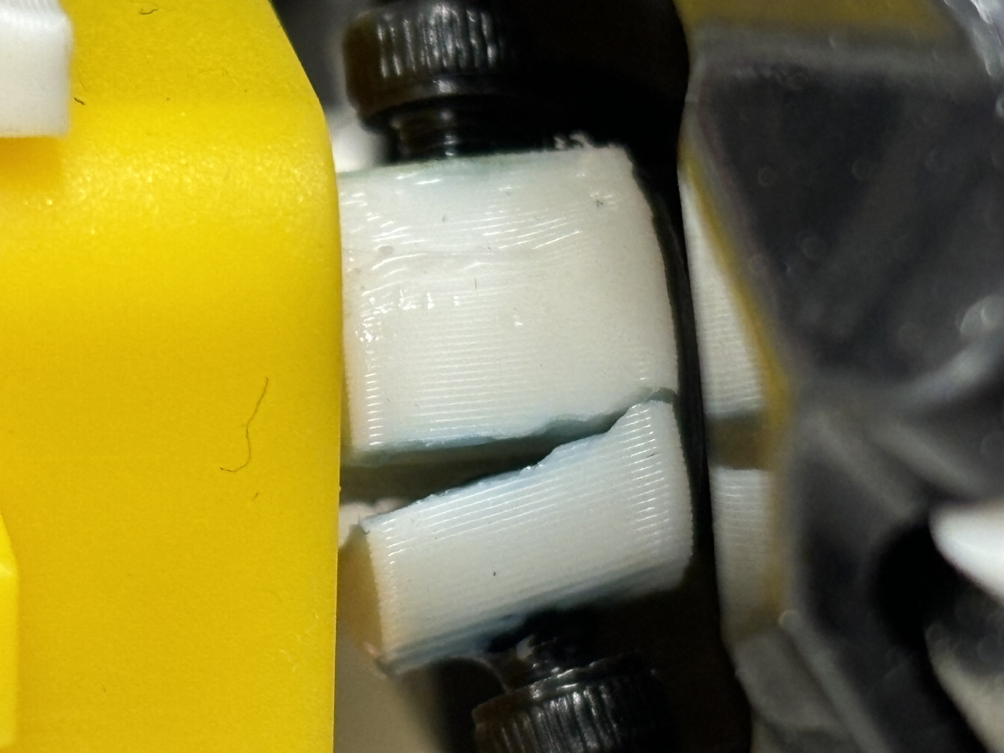
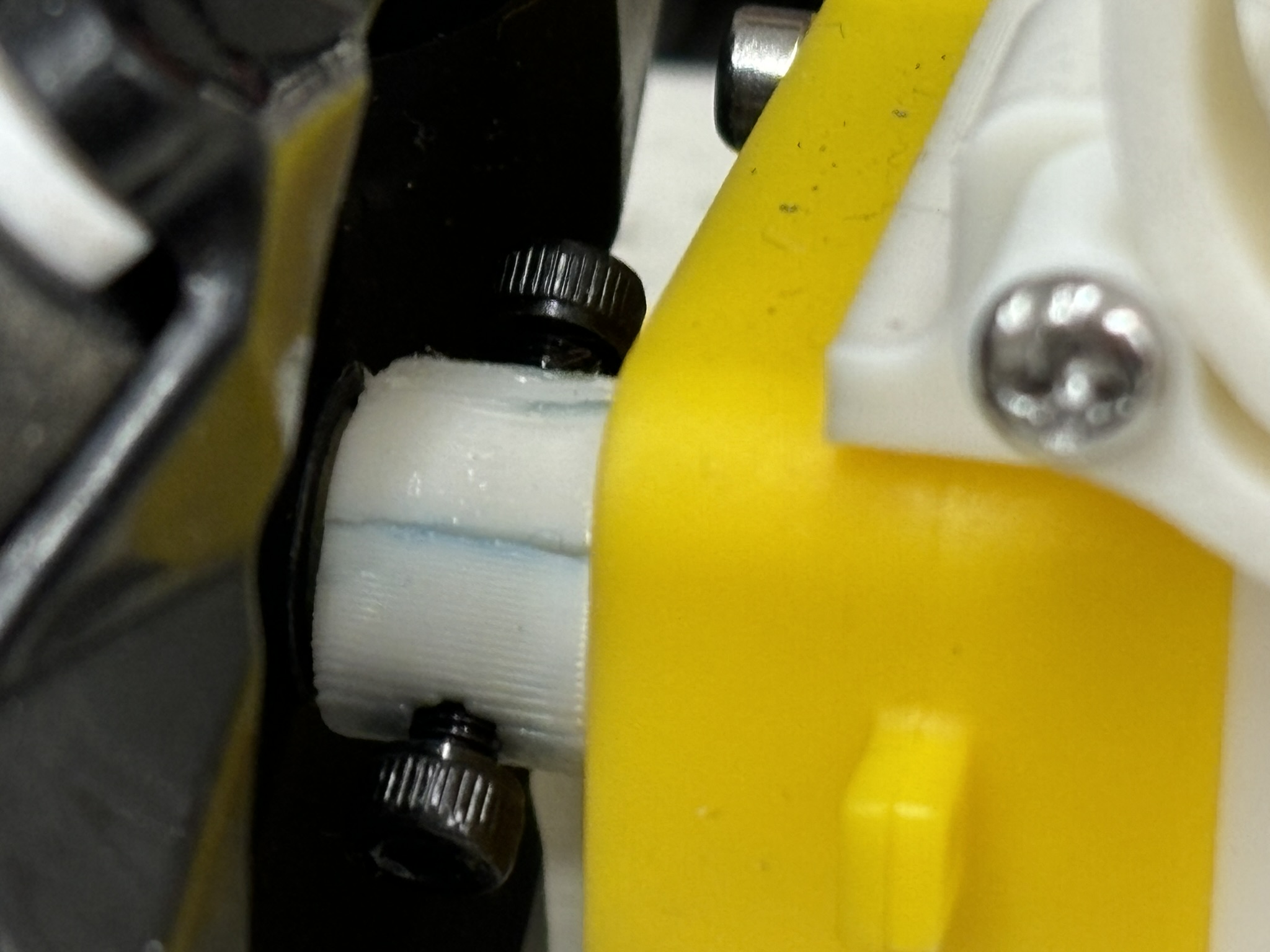
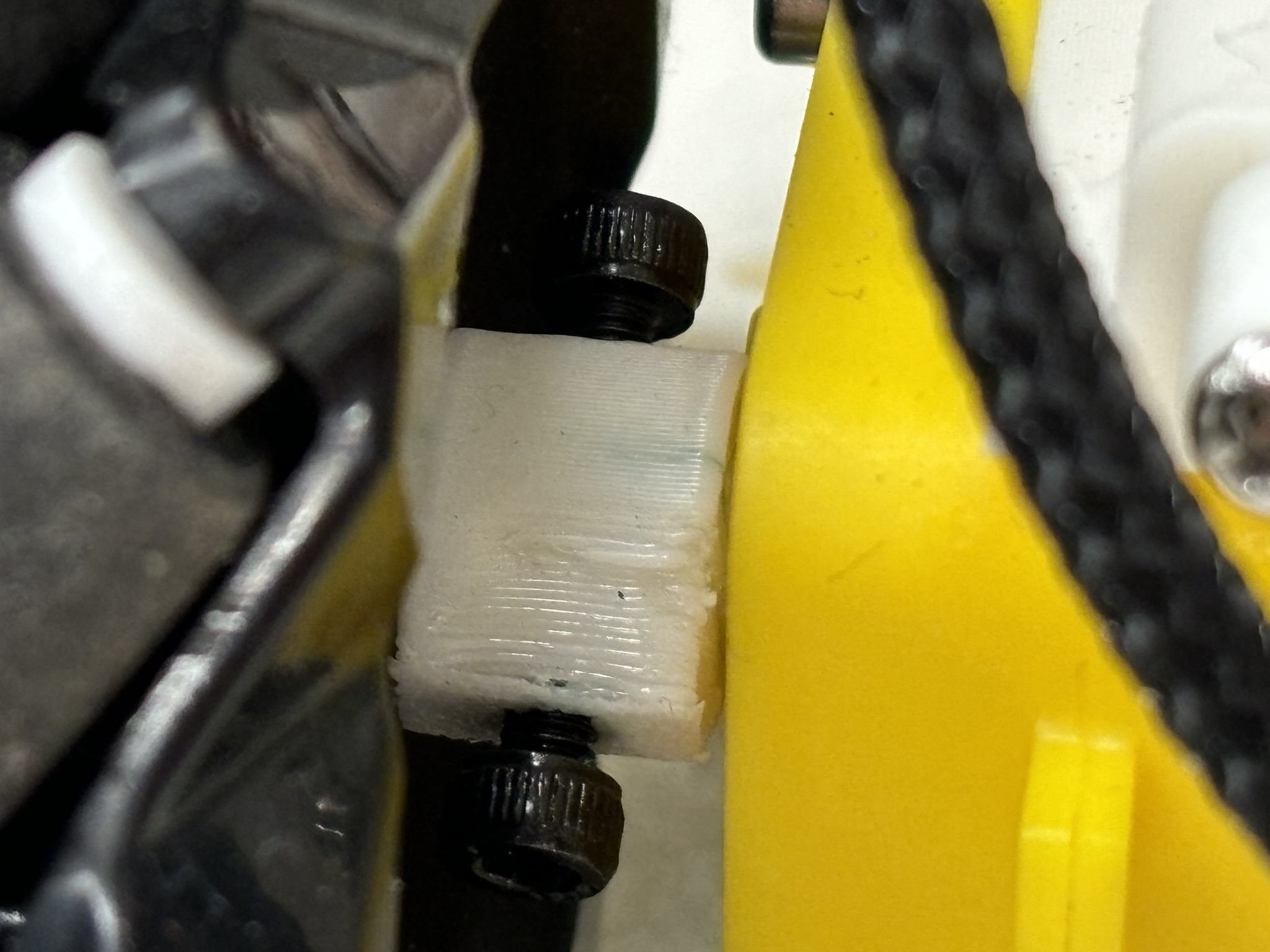
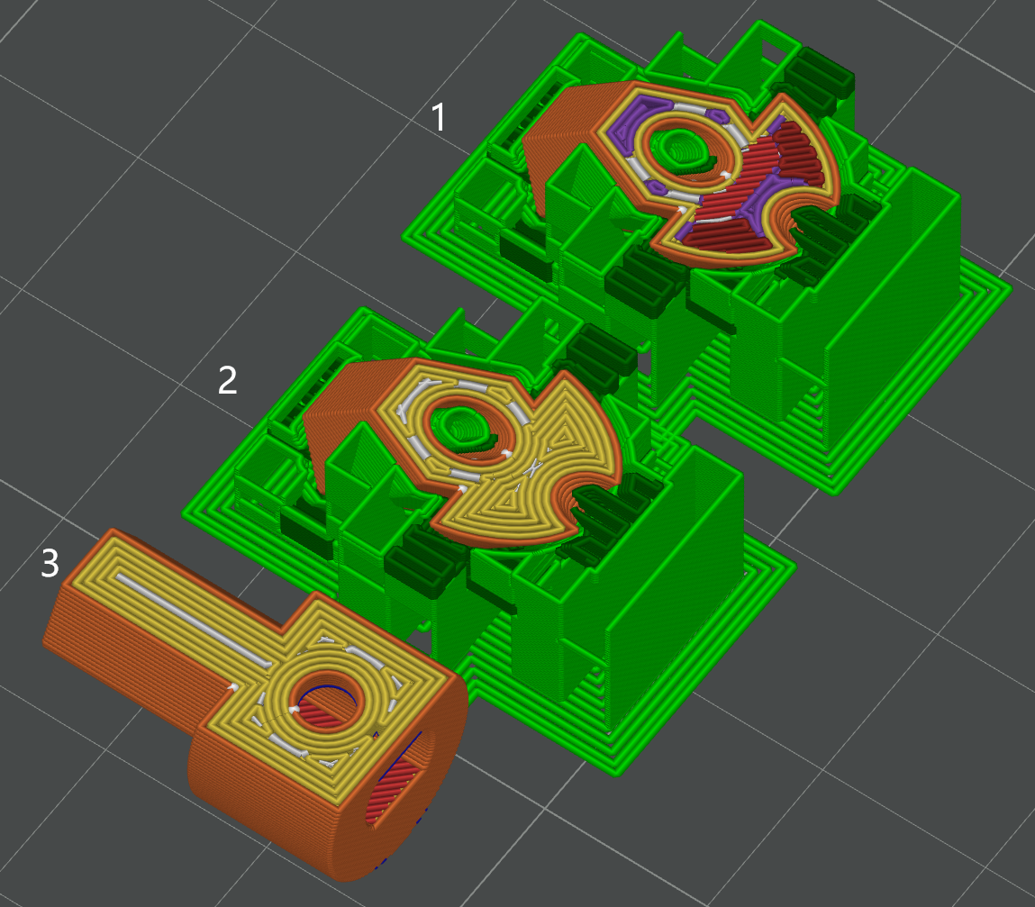
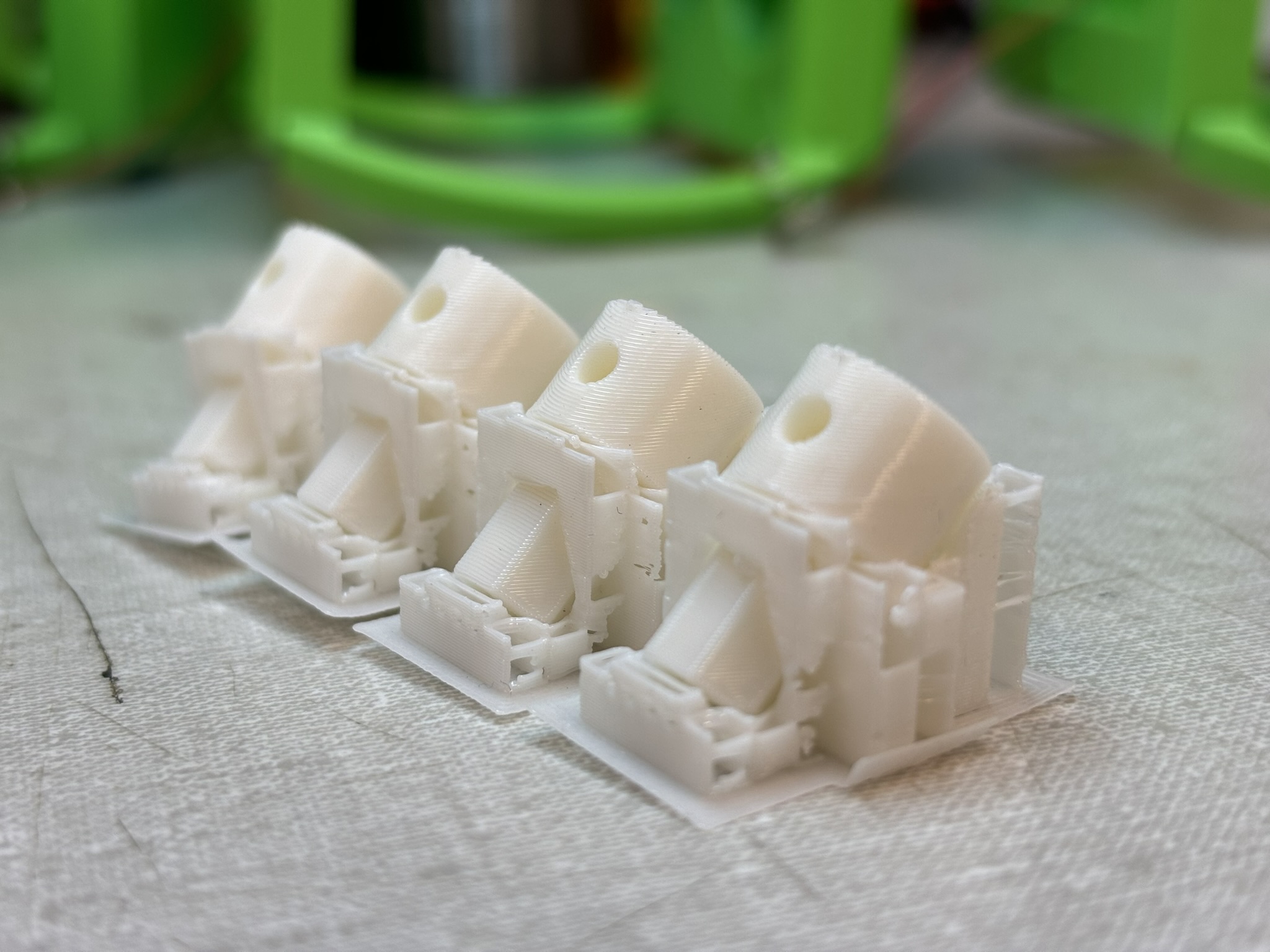
1.1.3. Spiral Spring
It is inspired by a 3D printed mangonel. Why am I not using the spring from the kit?
- It’s hard to find the spring with the right spring constant. It’s possible to find one, but it needs iteration.
- Extension springs will increase the suspension size.
- Rubber band could break during the cold weather transfer.
- Compression springs need perfect slot fit, which is very hard for 3D printing. Also it needs both upper and lower limits
- I was thinking to use magnets, but it has the same issues.
1.2. Chassis
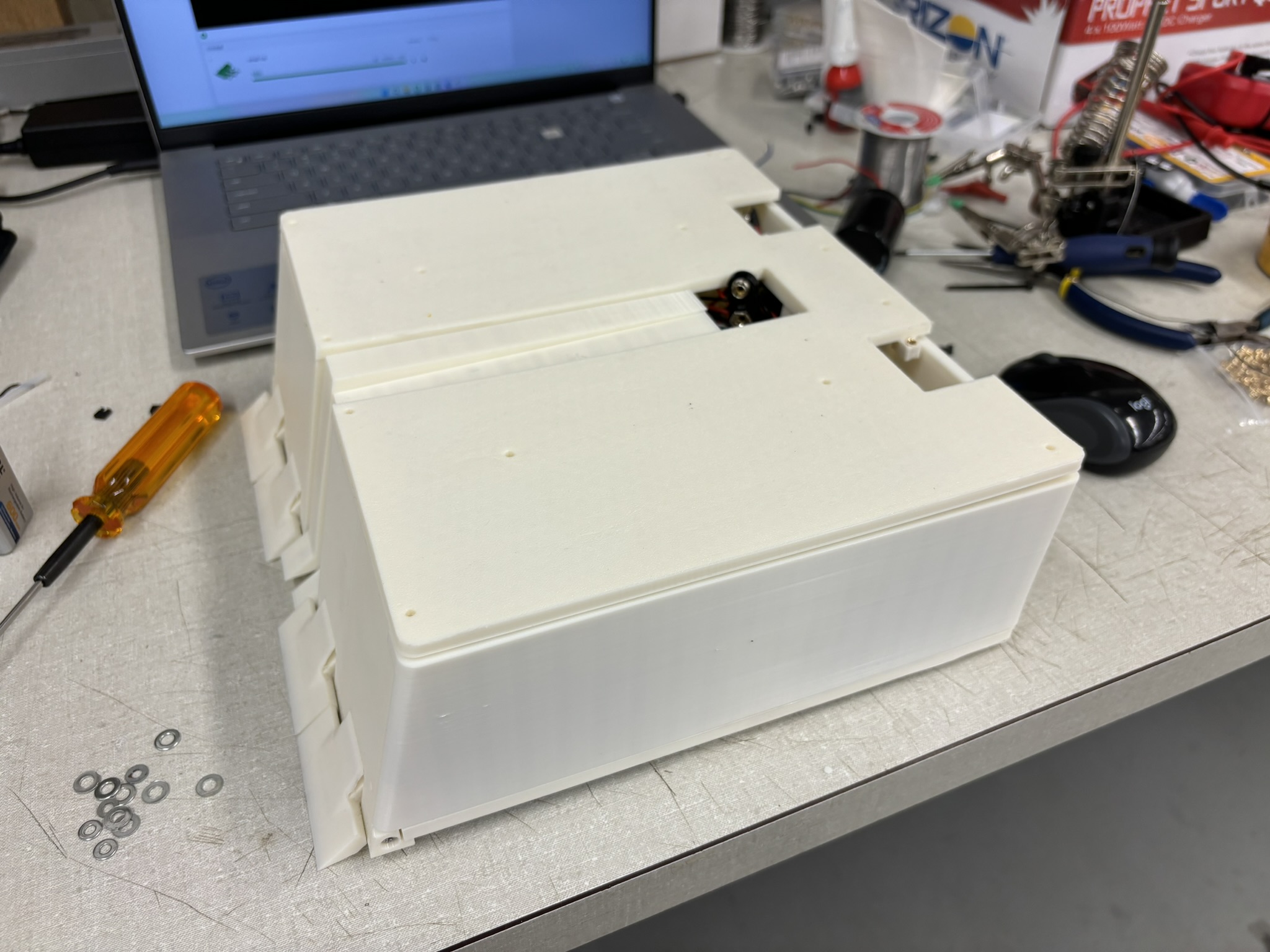
Chassis is one of the last parts I designed, because I need to know where things go. The thickness is 1/4 inch, so I can also laser cut an aluminum chassis if I want. I would do that if the final robot is not heavy enough, and if I see deadly vertical spinner. The 3D printed chassis has a high wall thickness, thicker bottom and top layers, and higher density tri-hexagonal infill pattern. Putting all things together is hard due to the size limit.
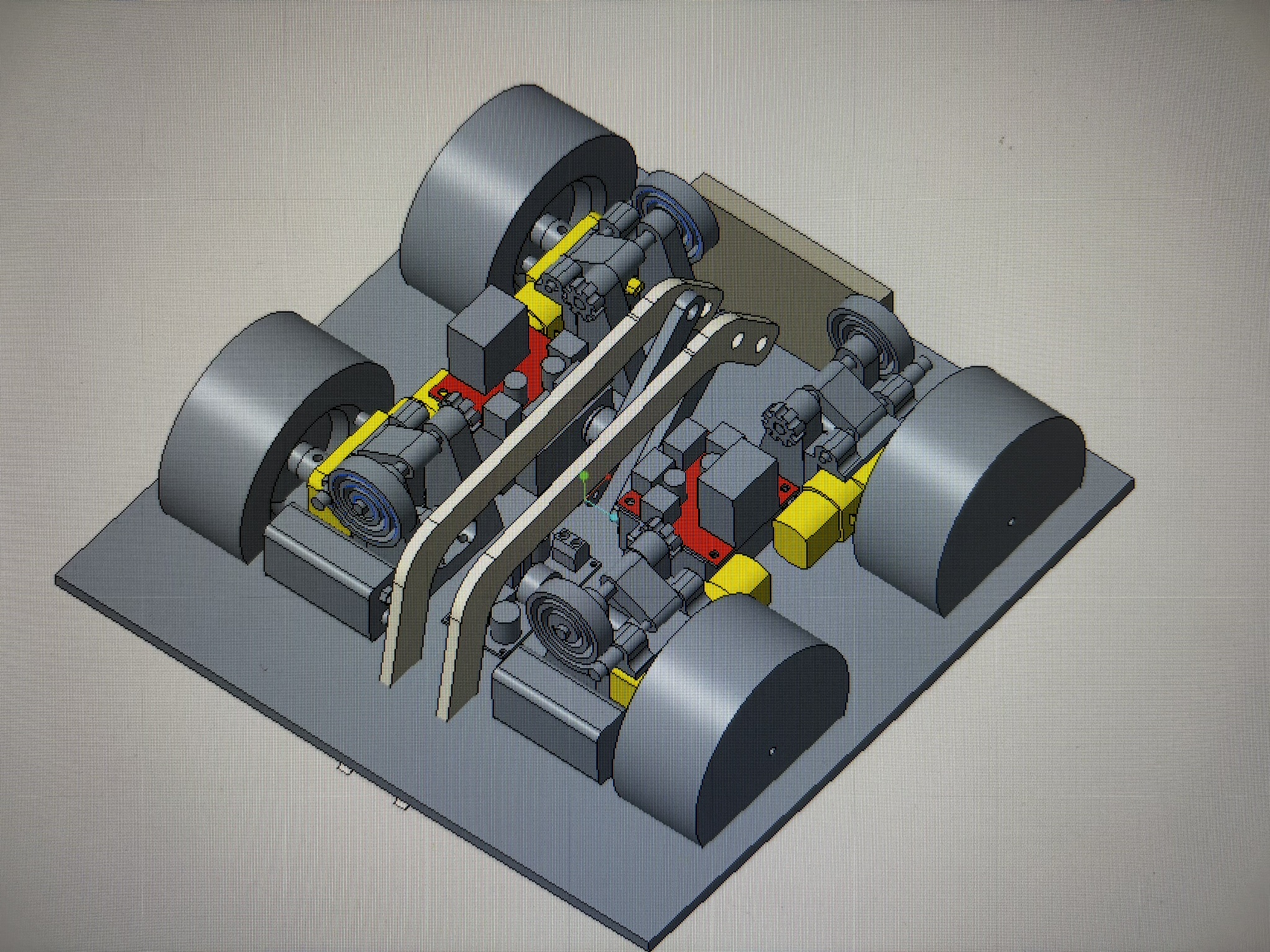
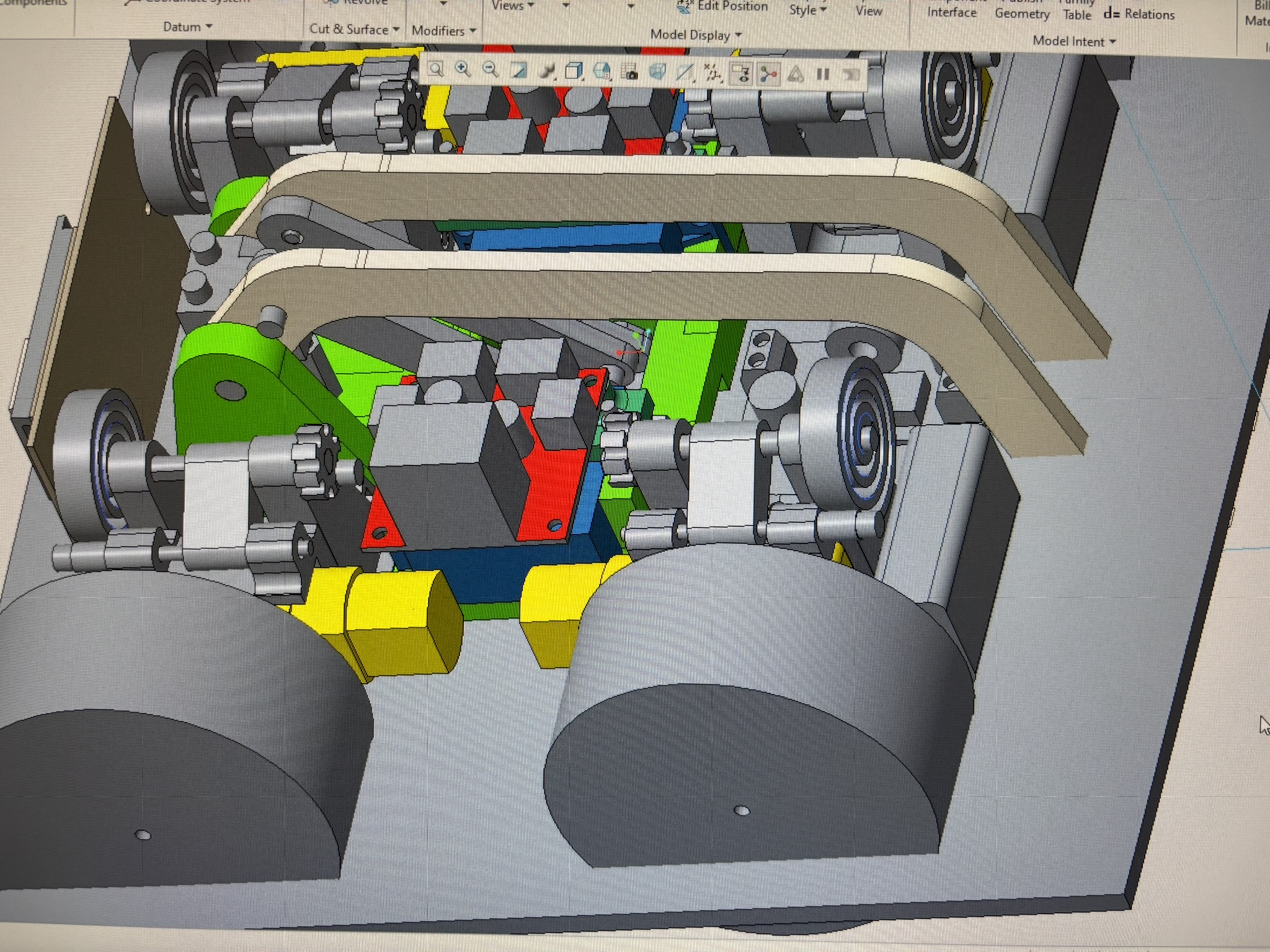
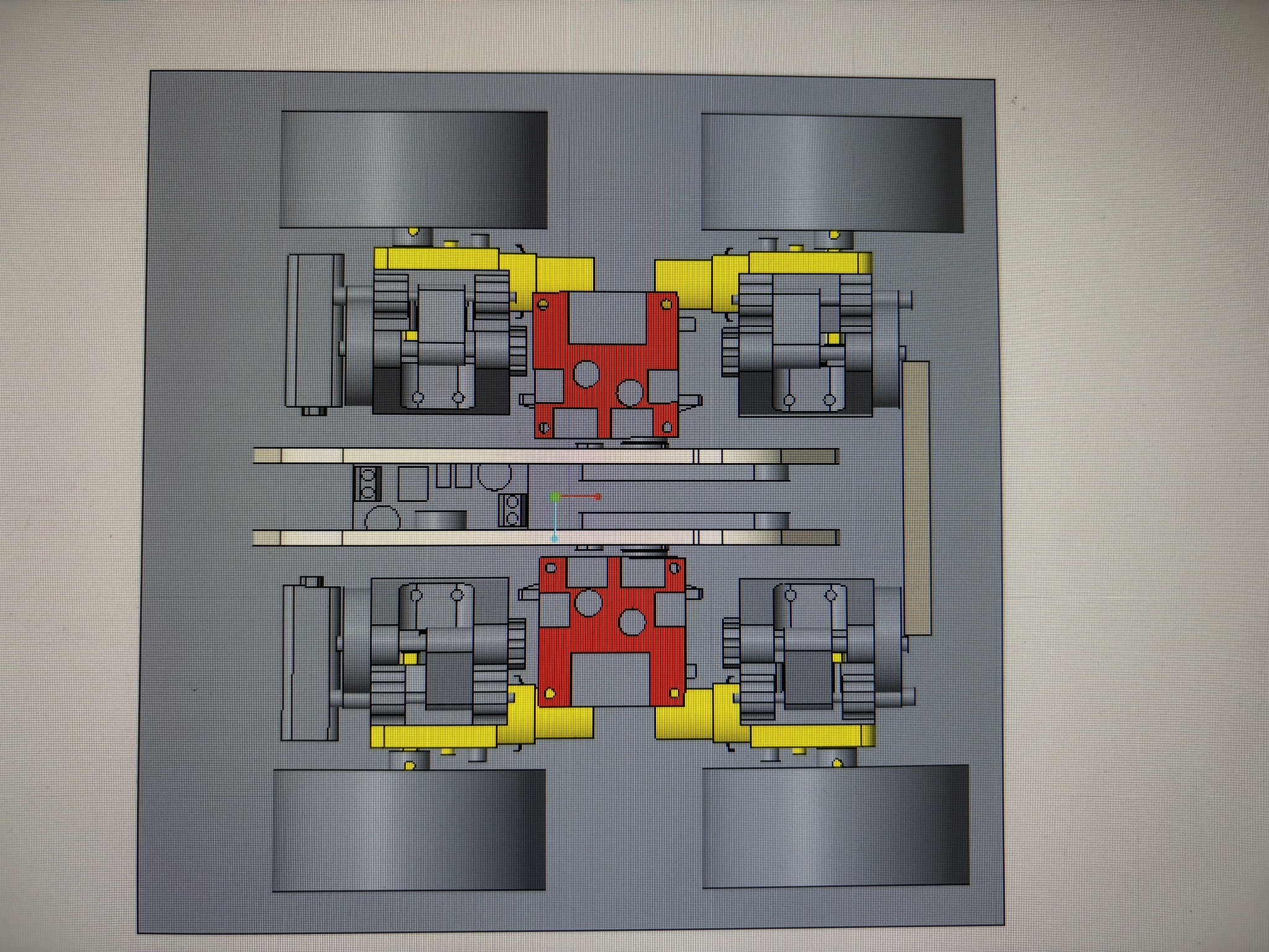
1.3. The Weapon Flipper: Two Designs
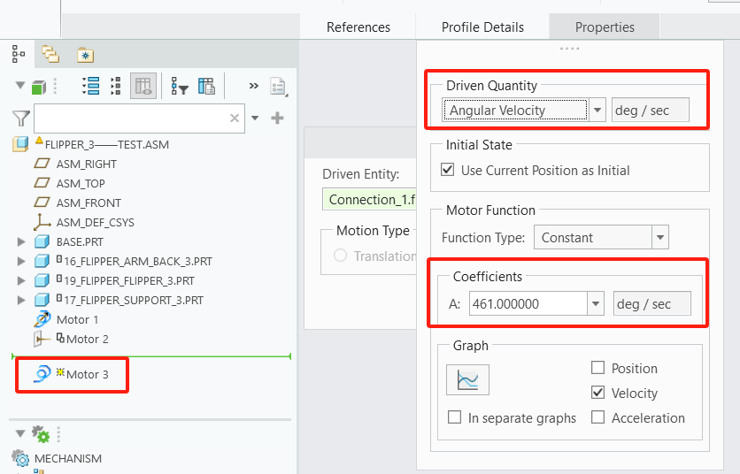
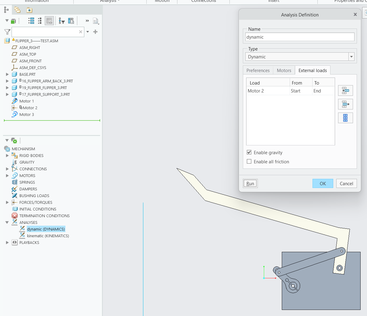
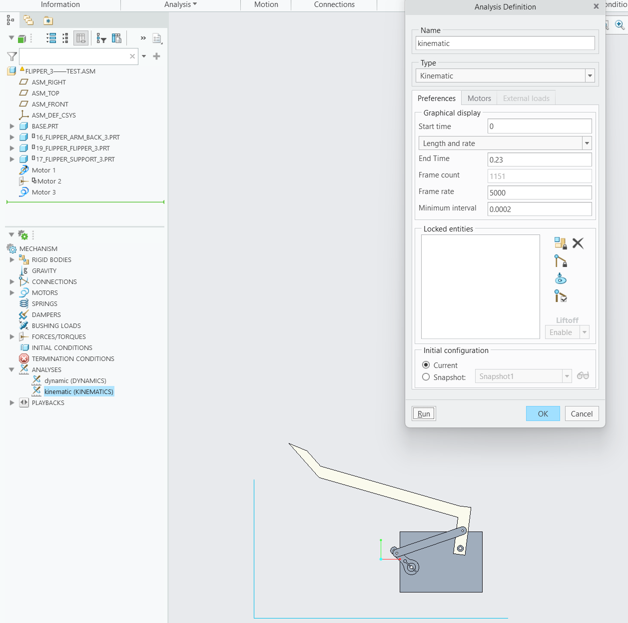
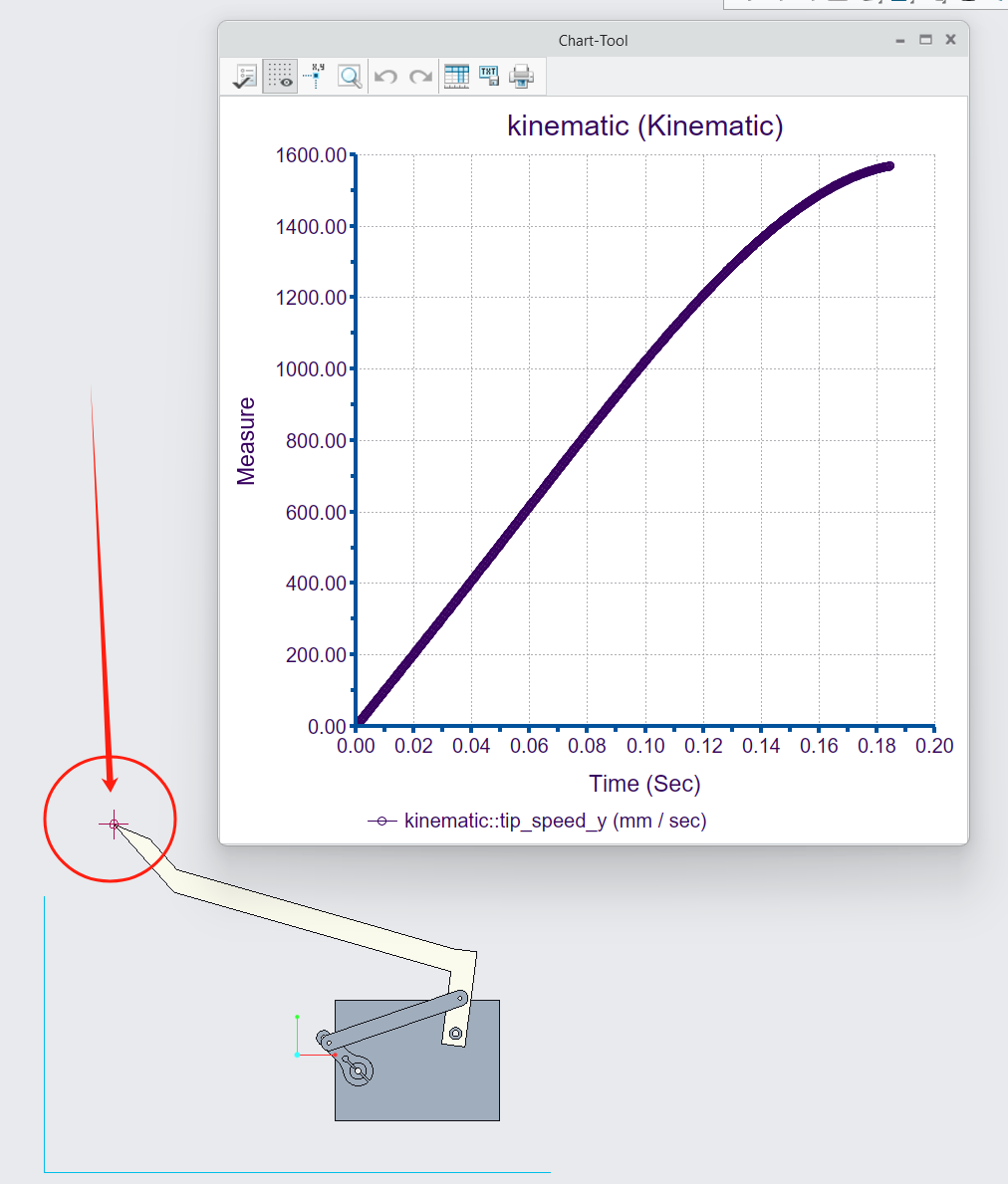
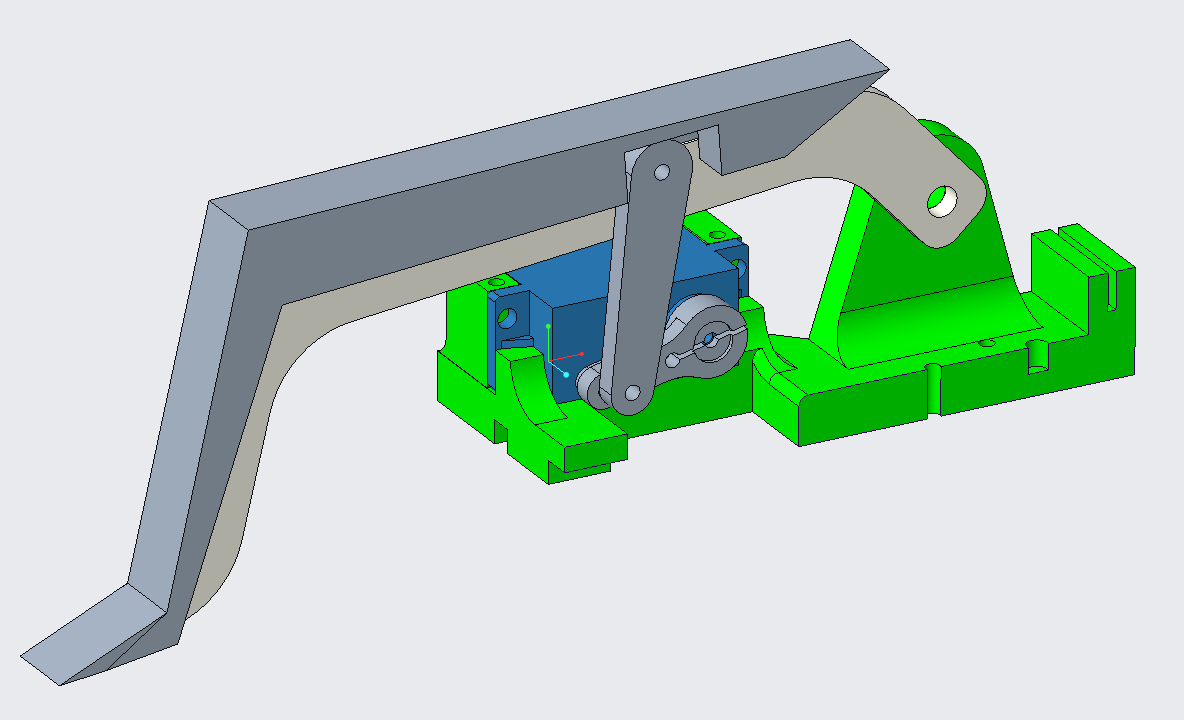
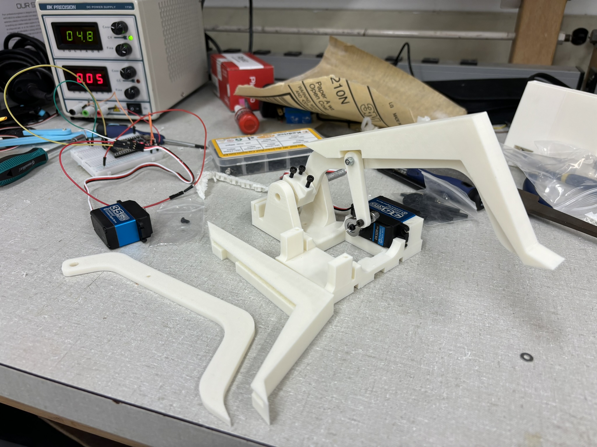
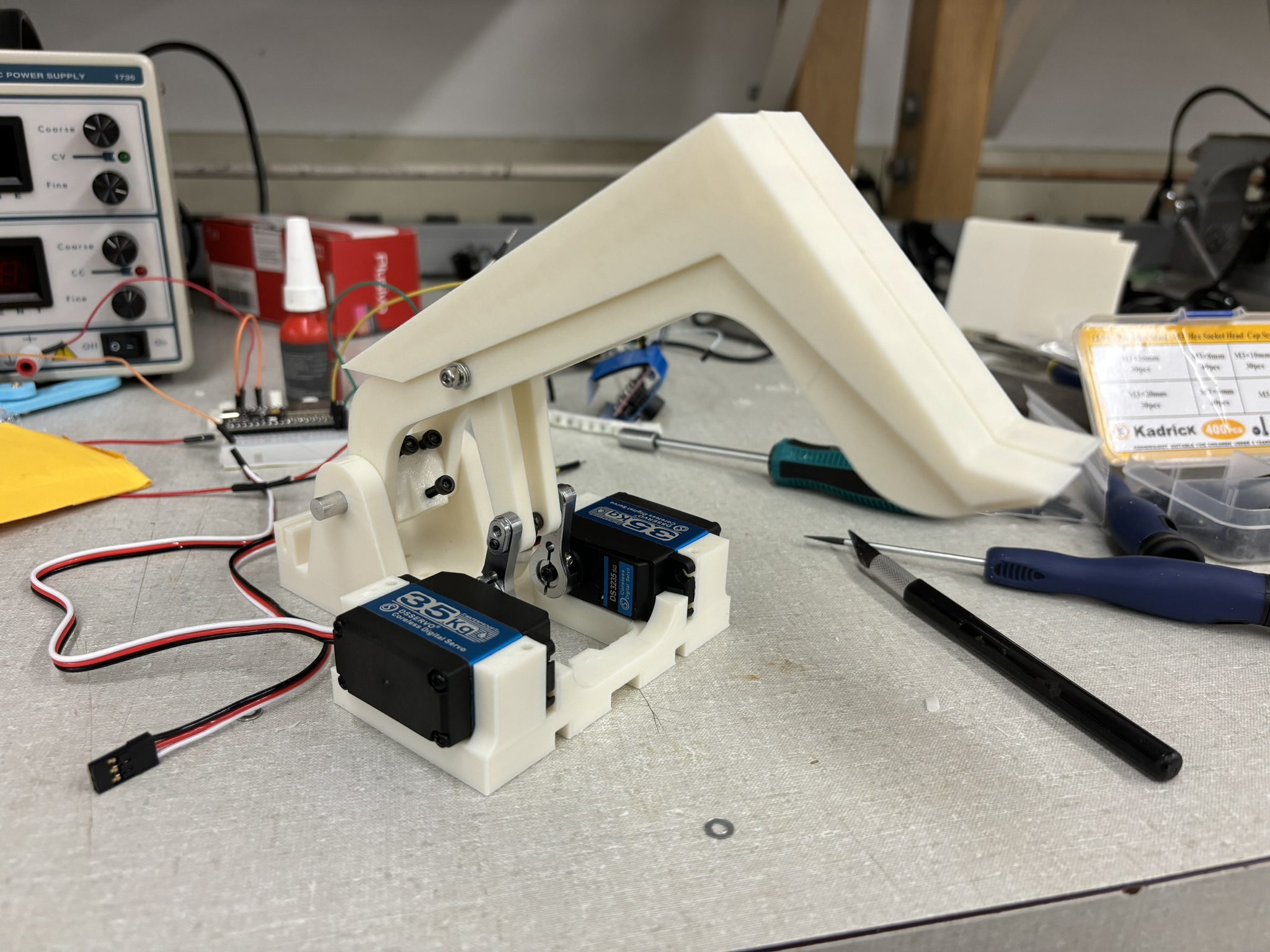
Initially I had a flipper design with the small 2 kg-cm servos, then I knew there’s no limitation on the motors, so I ordered two 35 kg-cm servos. According to the product description, the servo should have the rotation speed of 0.13sec/60 degree (461 degree/second) at 5V, but it’s a SCAM! It’s so slow even at 7.4V. In the original design, the flipper should be fast enough to launch a 1.5 kg object 30 cm above the ground, but I can’t do nothing with this super slow servo, so I change the strategy to heavy-lifting. It shouldn’t be a problem to lift any robots with two 35 kg-cm servos.
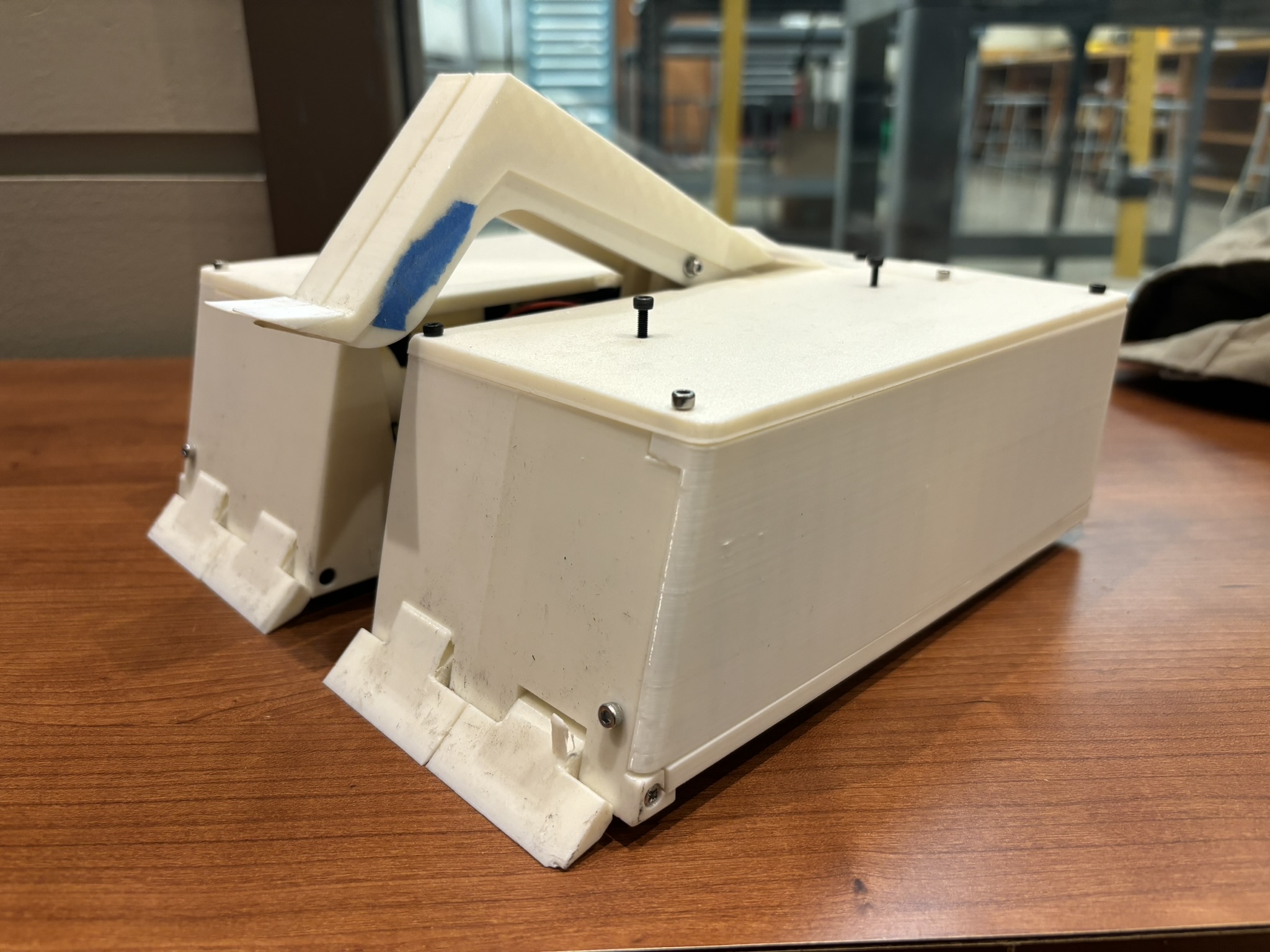
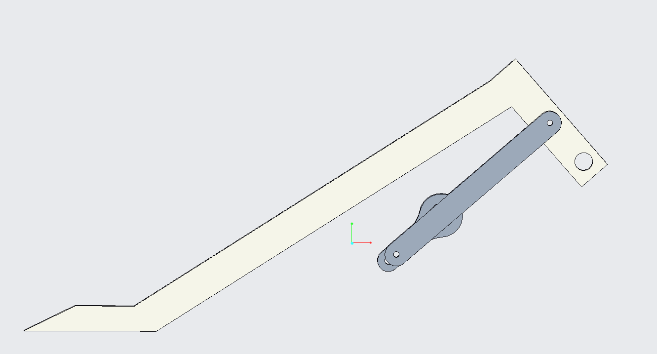
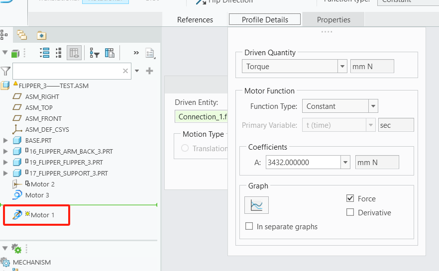
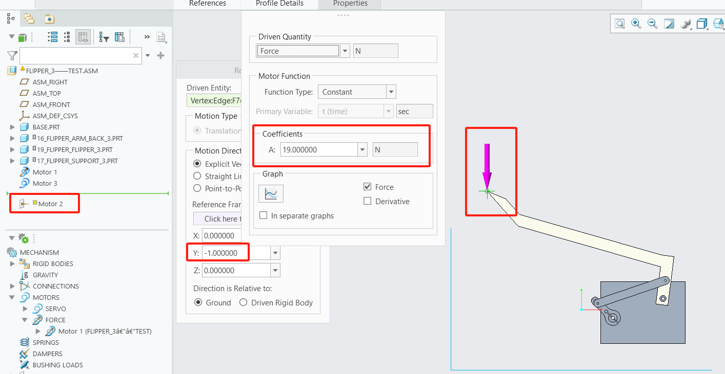
The flipper is a four bar linkage design. The design you see in the picture is the result after hundreds of iterations (sometimes Creo has a bug and it just won’t do the right math and lead me to the wrong way). As long as the relative position doesn’t change, the shape of flipper wouldn’t matter. The flipper parts were printed with wall thickness of 8 and high infill density. The joints on the servo arm are locked by the thread locker so it won’t tighten the linkage when rotating.
The tip of the flipper is printed with TPU, a very soft material. If the robot collides with the tip of the flipper, it will deform and protect the part behind it (Figure 1.3.08).
1.4. Armors
I was using aluminum sheet to build the armor last time, but it needs to convert to inches, put into AutoCAD, mark the color, export file, go the machine shop, and do the post processing. It also need a skeleton. This time, I am just using the toughness of PETG.
1.4.1. Front Armor
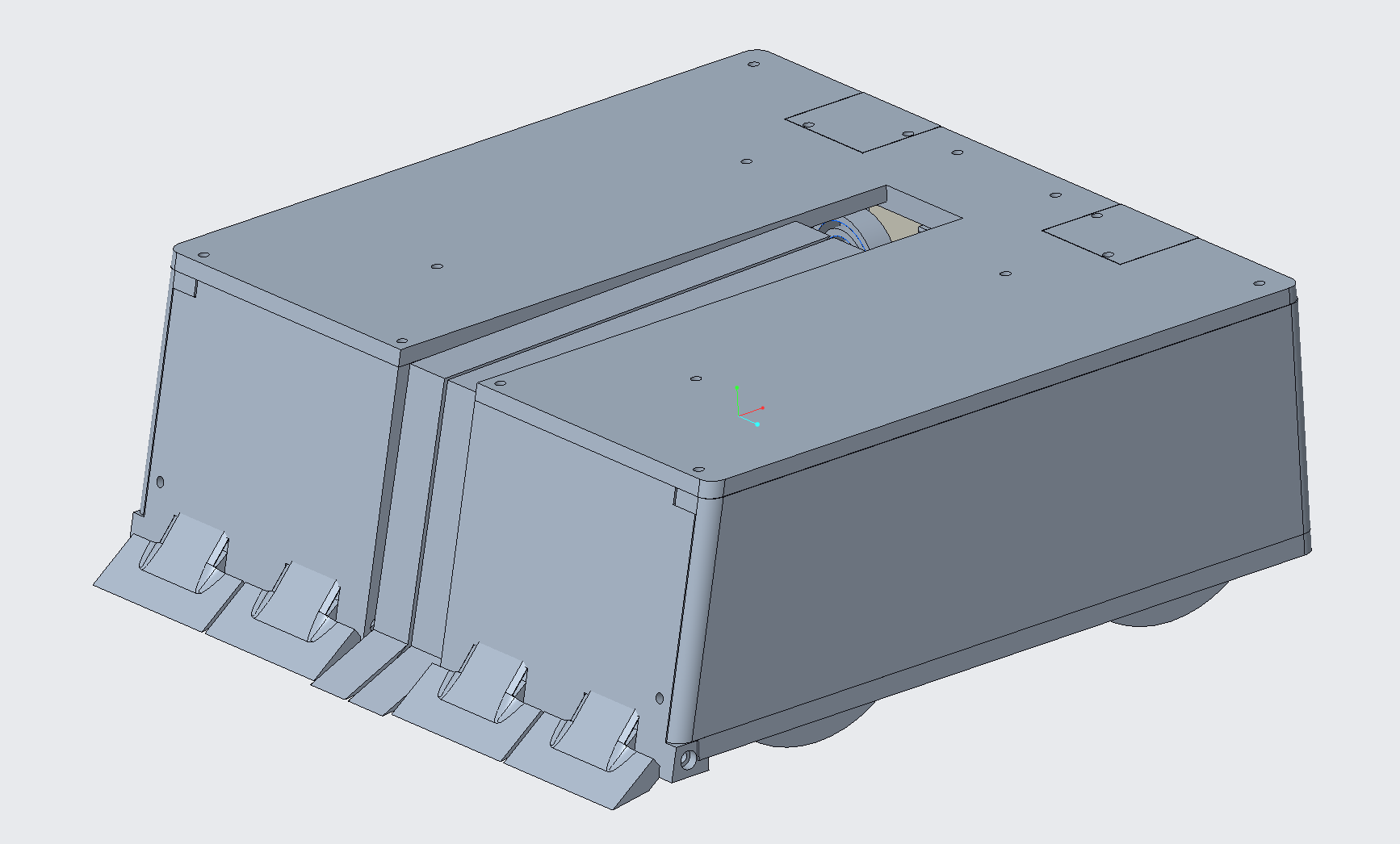
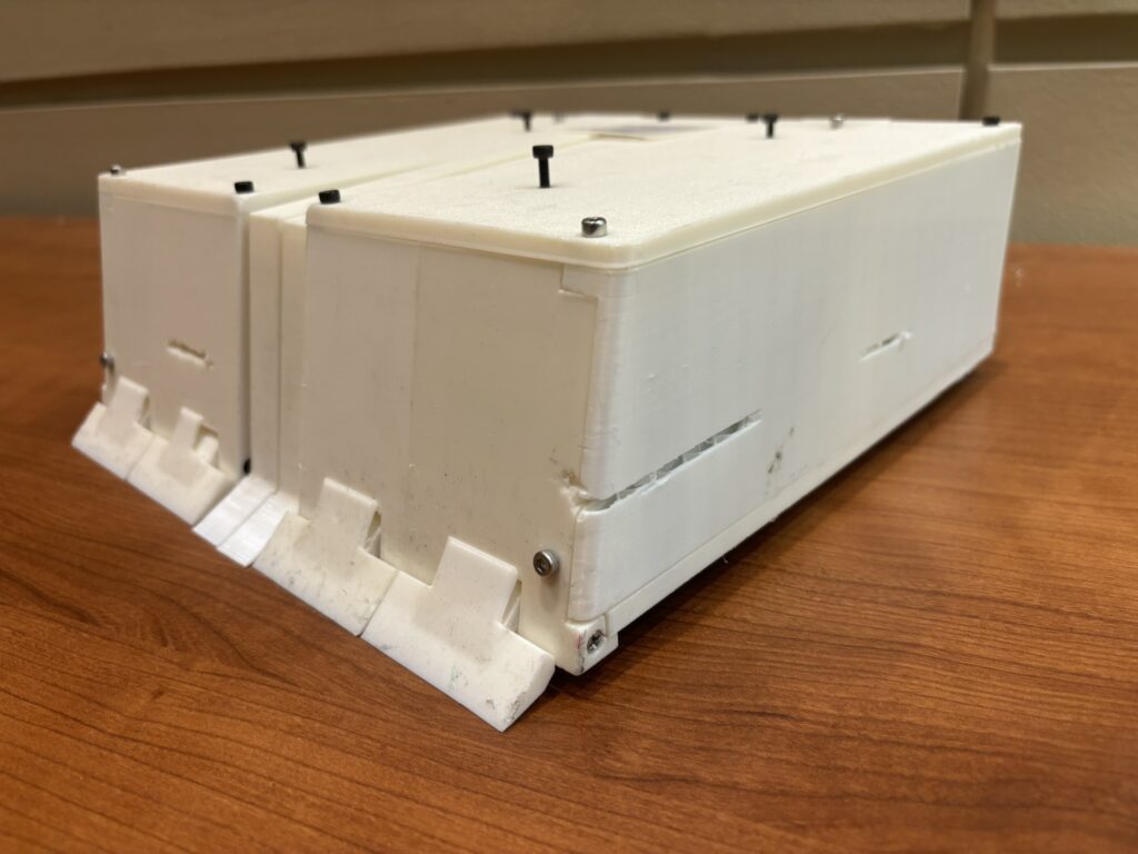
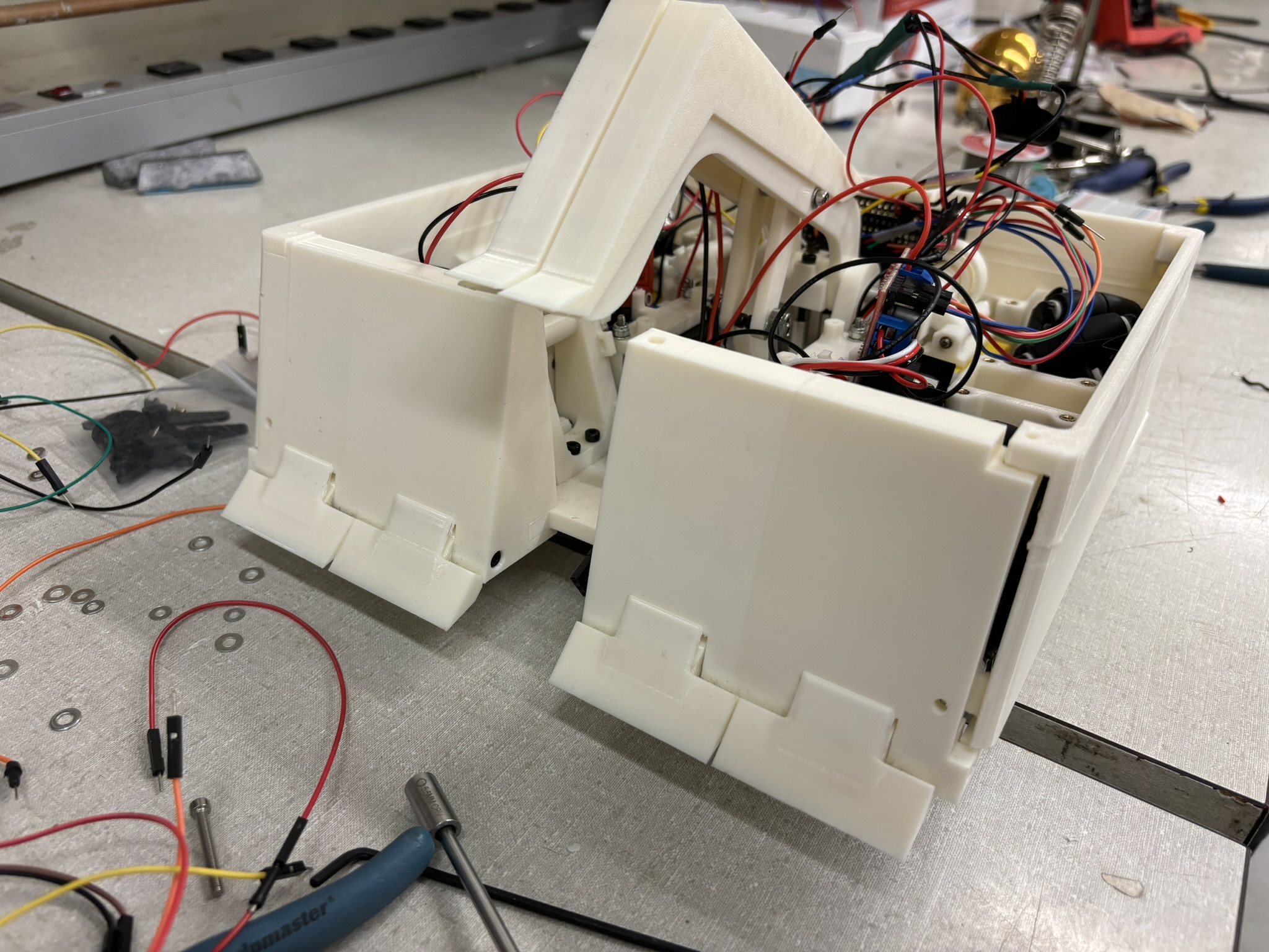
Front armor is the most important one. Sloped armor is used again with steeper angle due to the size limit. It’s printed with the wall thickness of 4 with high infill density, results a mass of almost 200 grams. It also has slopes that is pressed to the ground by the weight of the robot when suspension is unlocked (there’s a spring-like components that’s pushing against the front armor and printed in one piece to make sure the slope is touching the ground all the time), so not only it’s pushing all the dust on the floor, the slope will also get under the opponents so the flipper can lift it up. The flipper is a little bit behind the front armor, so the crash won’t damage the flipper. The flipper is not designed for collision.
The front armor really did a good job when fighting.
1.4.2. Side and Back Armor
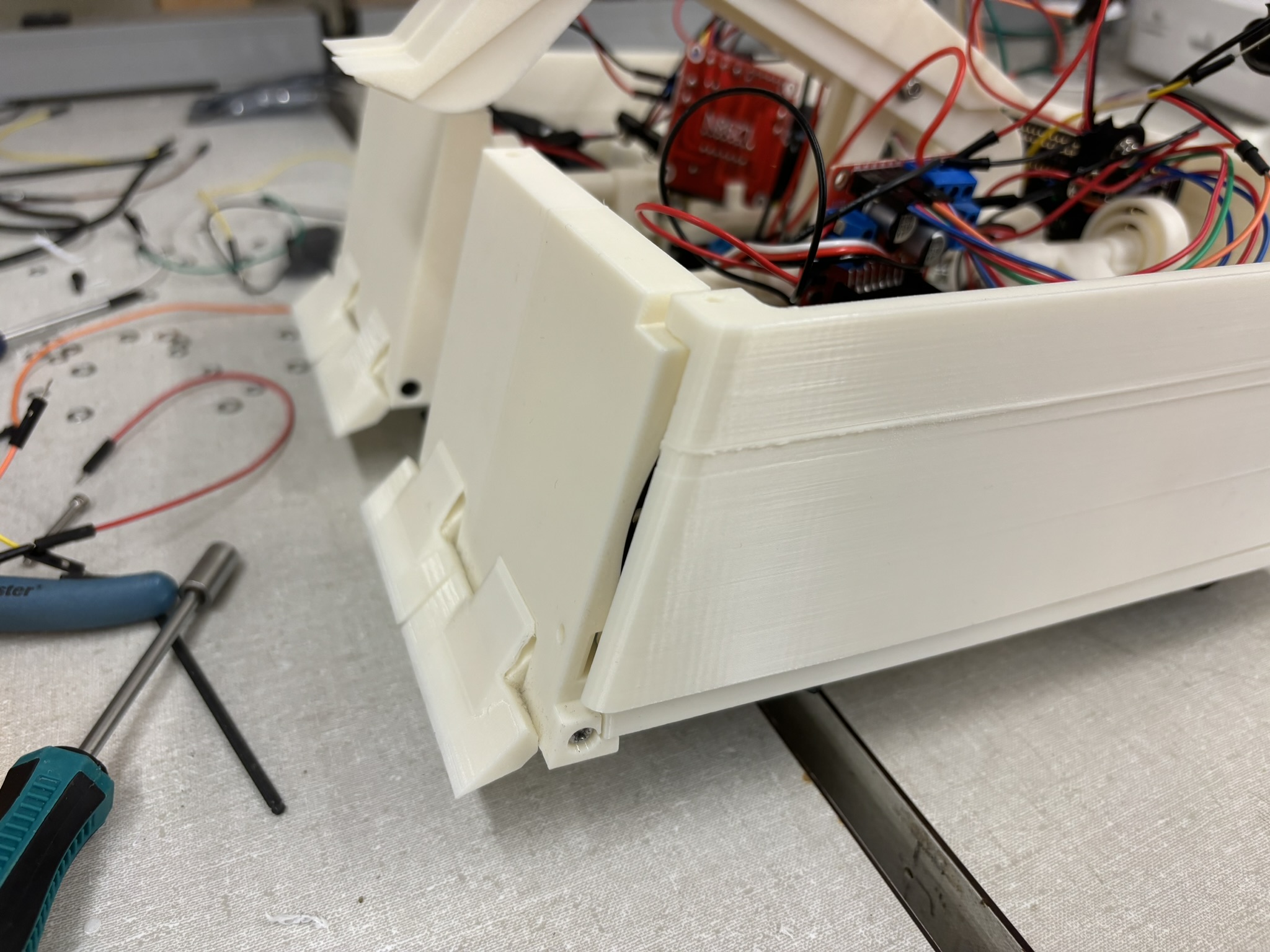
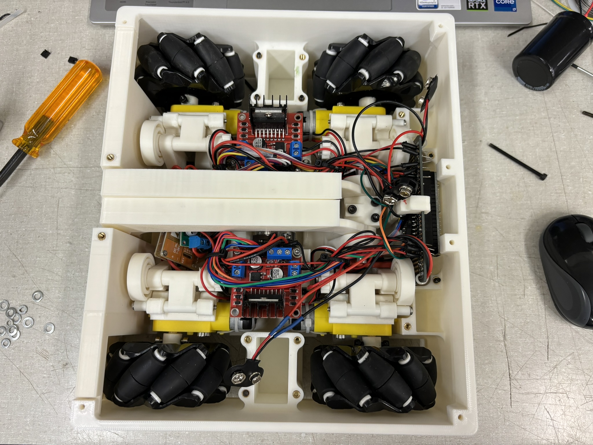
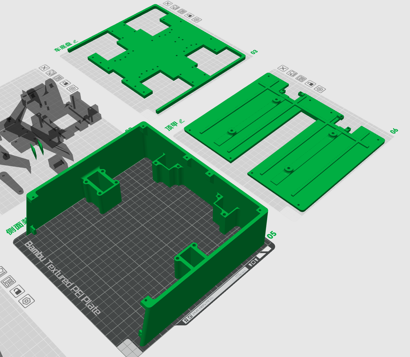
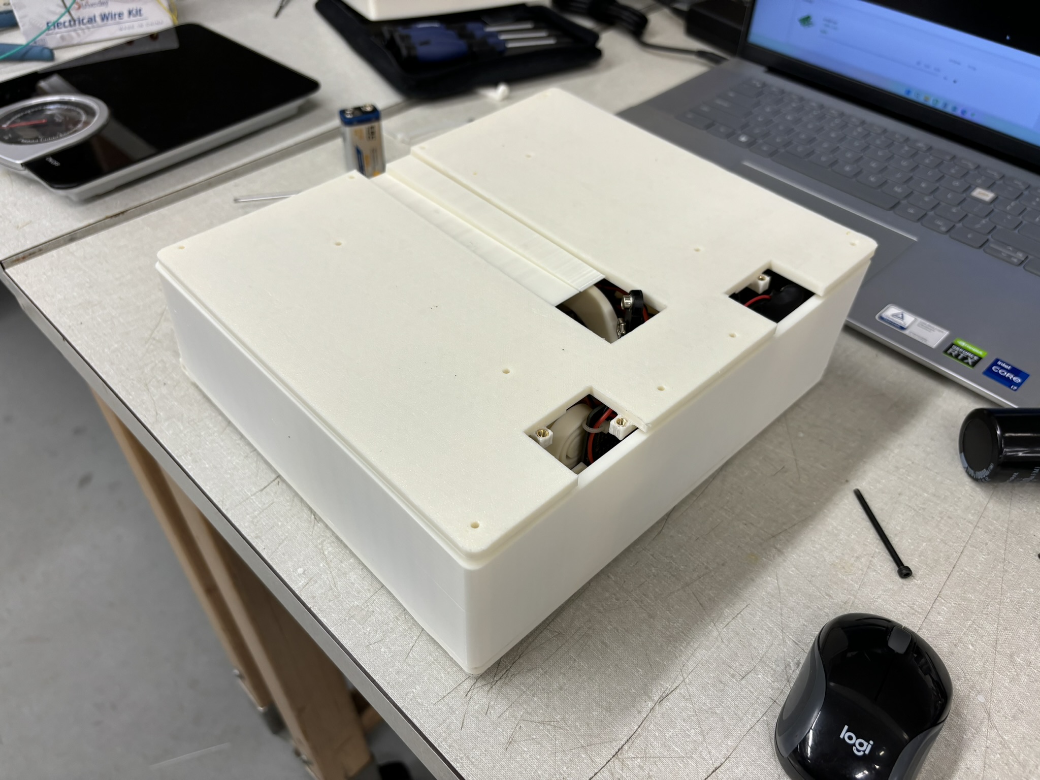
Side and back armor is built in one piece. I was planning to build it with TPU, but it requires 22 hours of printing, so I gave up and used PETG. The side armor connects the chassis, front armor, and top armor. It has the space to install the battery (back) and weights (side) if necessary.
1.4.3. Top Armor
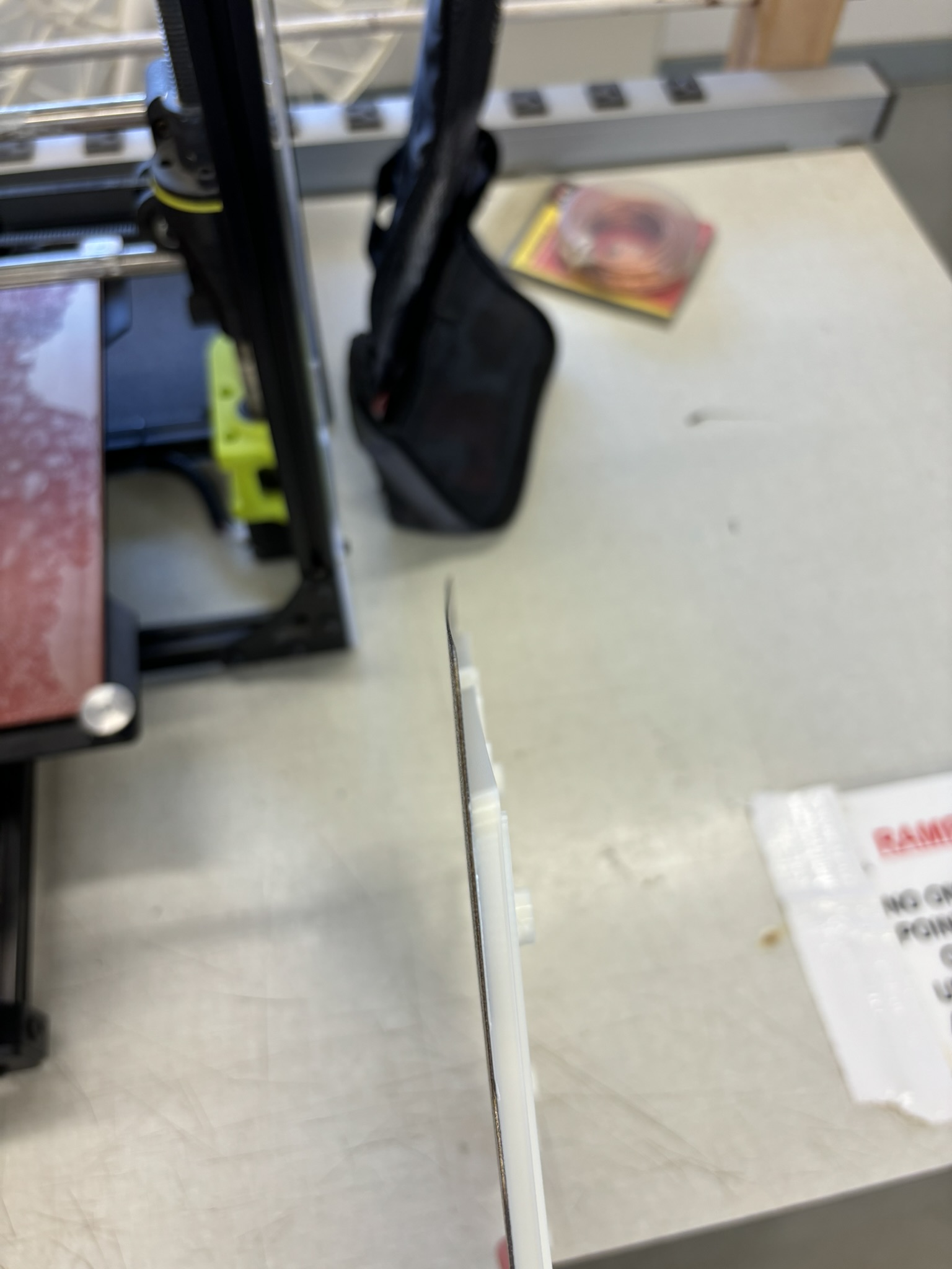
Sometimes the top armor will be loaded because the suspension is adjusted through there, so I added ribs on it. Since it’s a giant plate, and I need to remove it when it’s hot so I can keep printing the next one, the plate cools too quickly and bends, and it needs the annealing process.
2. Electronics
I don’t think a whole circuit diagram is necessary. Nothing fancy. The only thing I want to point out is that voltage regulator doesn’t use float ground.
2.1. Motors, servos, ESP32, Battery, Jump Wires, and Solderable Beadboard
- Motors: regular DC motors with a yellow gear box. The wire of the motors were pre-soldered with jump wires. The tip of the jump wire is in “u” shape, so it will crack if you bend it. That’s why I cut off all the heads, do the wiring stripping, and tin the tips.
- Servos: are 35 kg-cm servos. I could use the 45 kg-cm ones, but that’s too expensive. The theoretical speed is 0.13 seconds per 60 degrees with 5 volts. Scam! Maybe I can try linear motors next time.
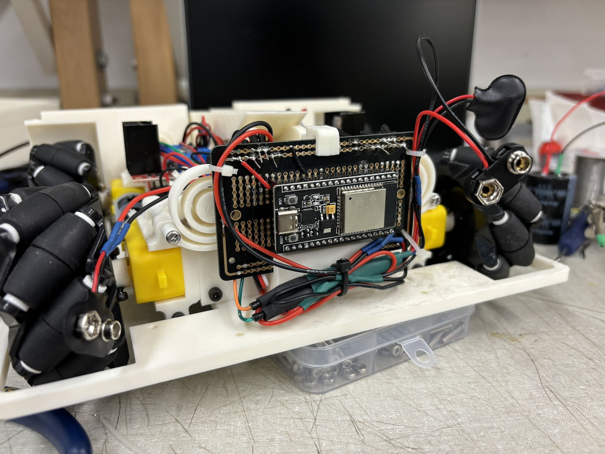
- ESP32: The one I bought has the type-C port, everything else is the same. It has a built in Bluetooth module, so make it useful! Note: some of the pins can only be used as input, and not every pin can be attached to servos (see this link, I couldn’t find the website I referenced). For these reasons, it took me so long to debug (Figure 2.1.01).
- Battery: is a 2s Li-ion battery, with the voltage range from 7.4V to 8.4V.
- If the battery experience a current that is greater than the limit, it will shut off itself.
- When the current is high, the measured voltage will drop a lot. If the voltage is below 7.4 V, it will shut off itself. This is more likely to happen when the voltage is low. Ex: when the motor is not running, the voltage is 7.6V. But when it’s running, the voltage could drop to 7.4 and cut the power. When you feel confused about this and measure the voltage, it will come back to 7.6V. That’s why many battery monitors on drones use both ammeter and voltmeter to calculate energy used.
- Jump wires were soldered together
- Solderable breadboard: it’s the key to prevent loose wire. And it’s thin so it saved a lot of space.

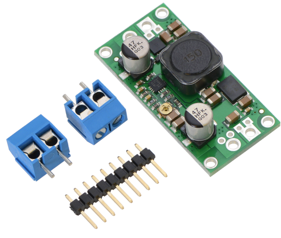
2.2. Pololu Adjustable 4-12V Step-Up/Step-Down Voltage Regulator S18V20AHV
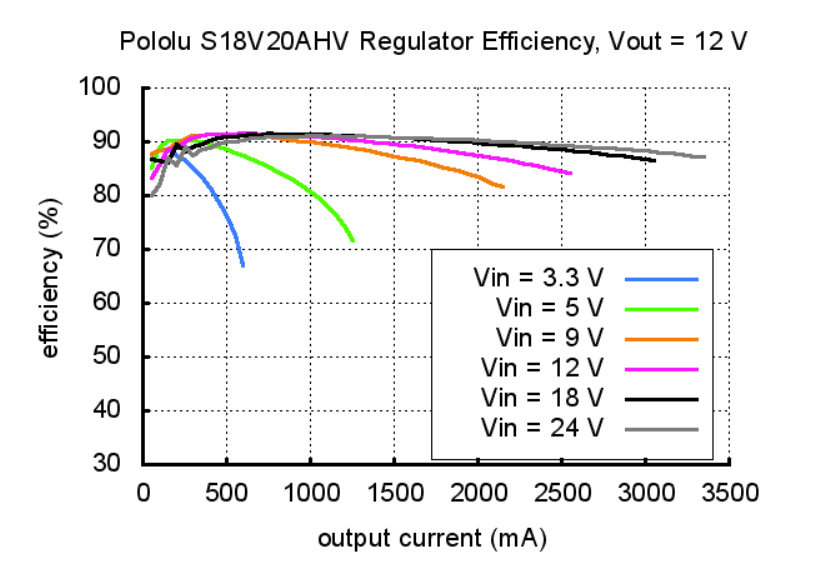
By adjusting the potentiometer, this voltage regulator will convert 3V-24V to 12V with a max current of 2A, so I don’t need one step-up for racing and one step-down for battle. Applying 12V to the motors is the reason why it’s so powerful. So, what the cost of powerful drive? The regulator has a max efficiency of 0.9, and the actual efficiency depends on the working condition (Figure 2.2.02). When using one 9V rechargeable battery, the efficiency curve is a little below the orange curve. There are two ways to connect two batteries for the battle, either series or parallel. Connecting batteries in series and using step-down would have a higher efficiency. Also, putting batteries in parallel has other issues, such as charging into each other. For the same power consumption, higher voltage can work with lower current, so this can avoid current overflow protection (which is very bad during battle).
2.3. Matek Systems UBEC DUO, 4A/5~12V & 4A/5V
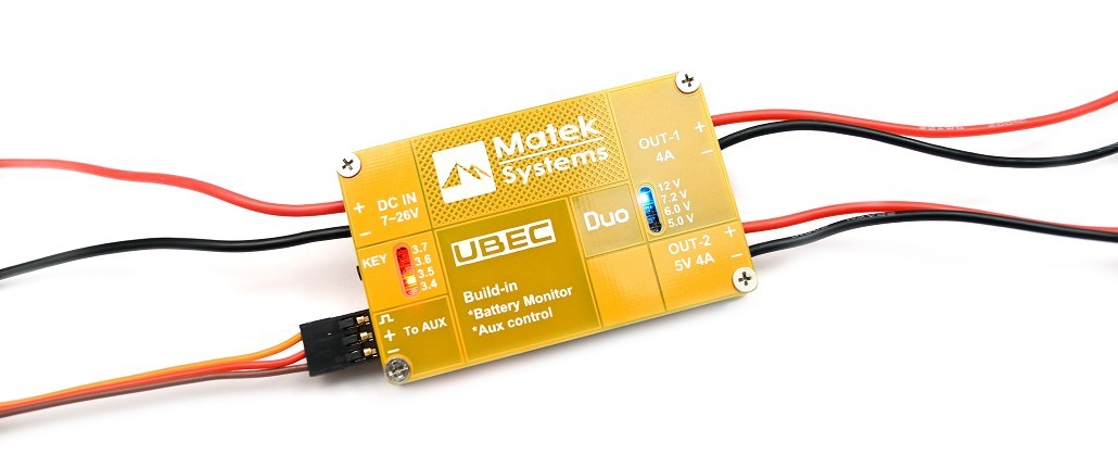
As discussed above, the current limitation can be solved by using series connection and step-down voltage regulator. But that’s for the wheels. Servos also consume a lot of current, usually around 300mA when not loaded on the servo I used. The current would be much higher when fighting. And there are two servos. ESP32 also need 5V. If there’s a 5V power shortage, ESP32 will restart by itself. I couldn’t find the max current output of LM298N, but the tests shows that two 5V output from LM298N can’t support two servos for sure (see videos below). So, I choose to use this battery elimination circuit (BEC) unit. It can provide 4A when outputting 5V. This is the same unit I used in RC Des Moines where it powered 11 small 2 kg-cm servos, Teensy 4.0, and three LEDs.
For some reason this BEC is fried when I’m trying to take the picture of bluetooth. Gonna test it later.
2.4. Voltage Monitor
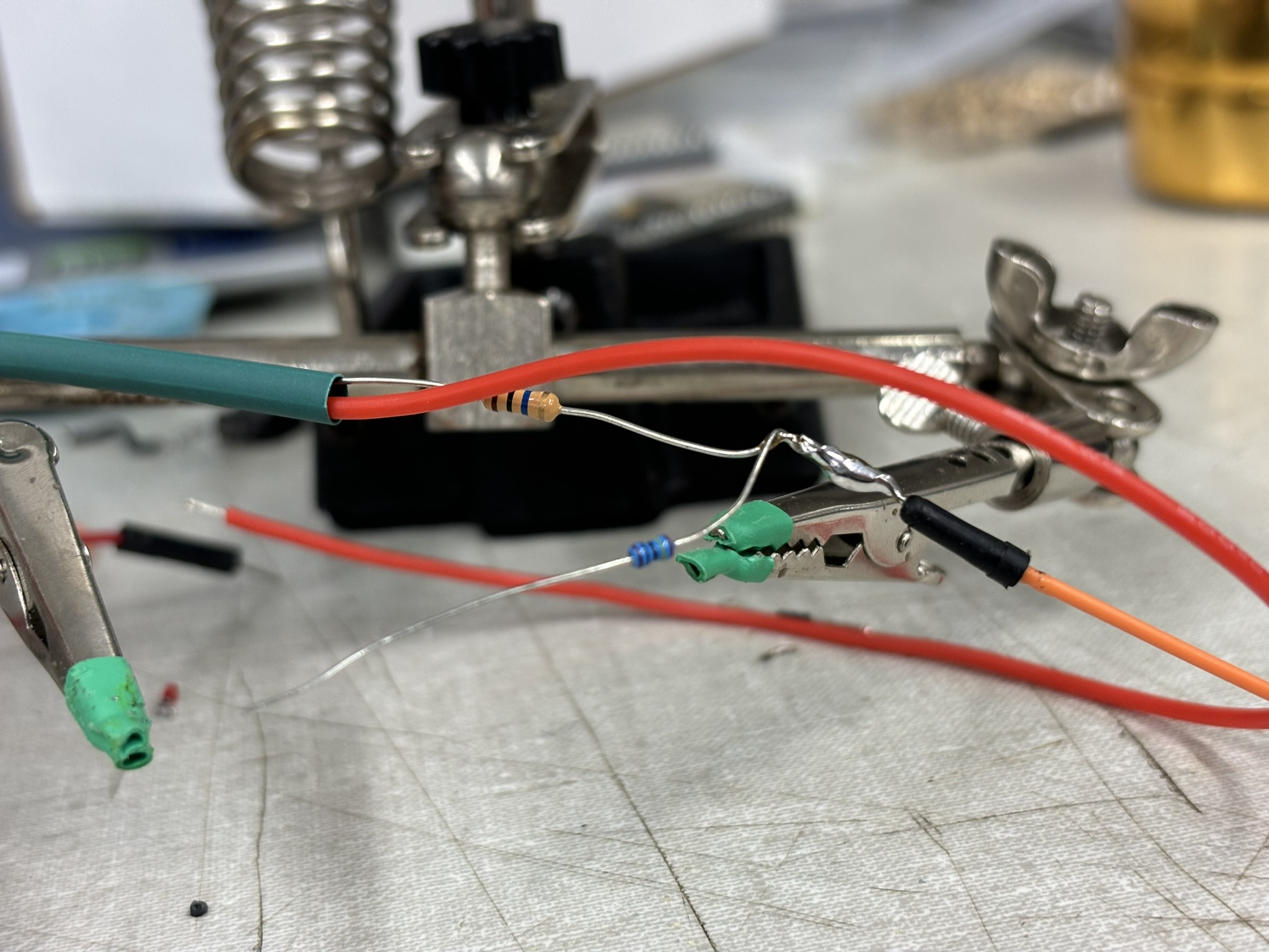
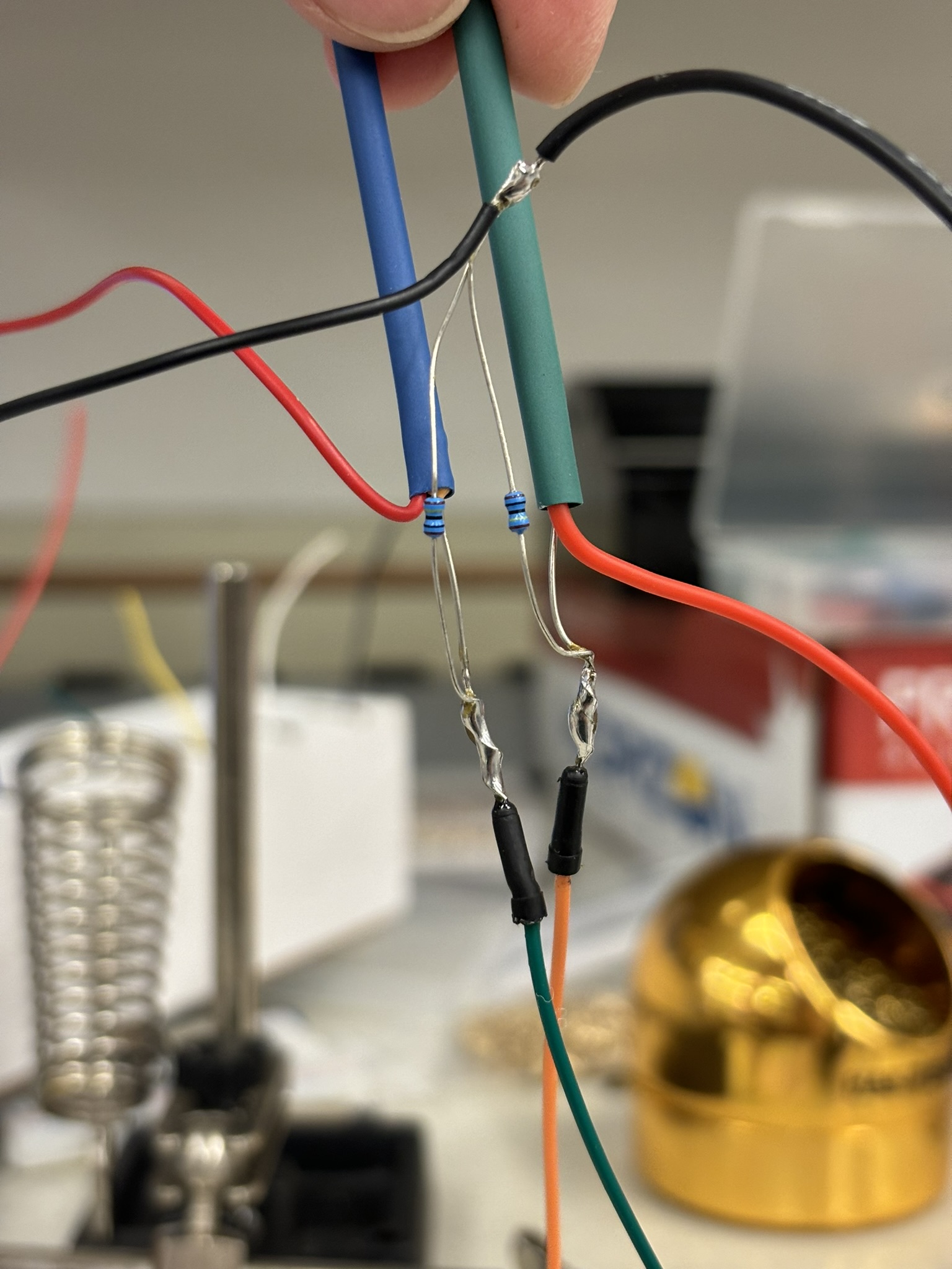
Knowing how much battery is left will give you confidence! Voltage monitor is achieved by using voltage divider with two 10Mohm and two 1Mohm resistors. In this way, the voltage can be reduced into the range of 0V to 3.3V. Then analogRead() function is used to read the value and converted to actual voltage (see equation below, where x is the value returned by analogRead() ). Reference link: ESP32 Analog Input with Arduino IDE | Random Nerd Tutorials. I didn’t have time to do the calibration, so there’s a roughly 2V difference between the value displayed and the actual battery voltage. But I can still use it as a reference.

2.5. Wiring
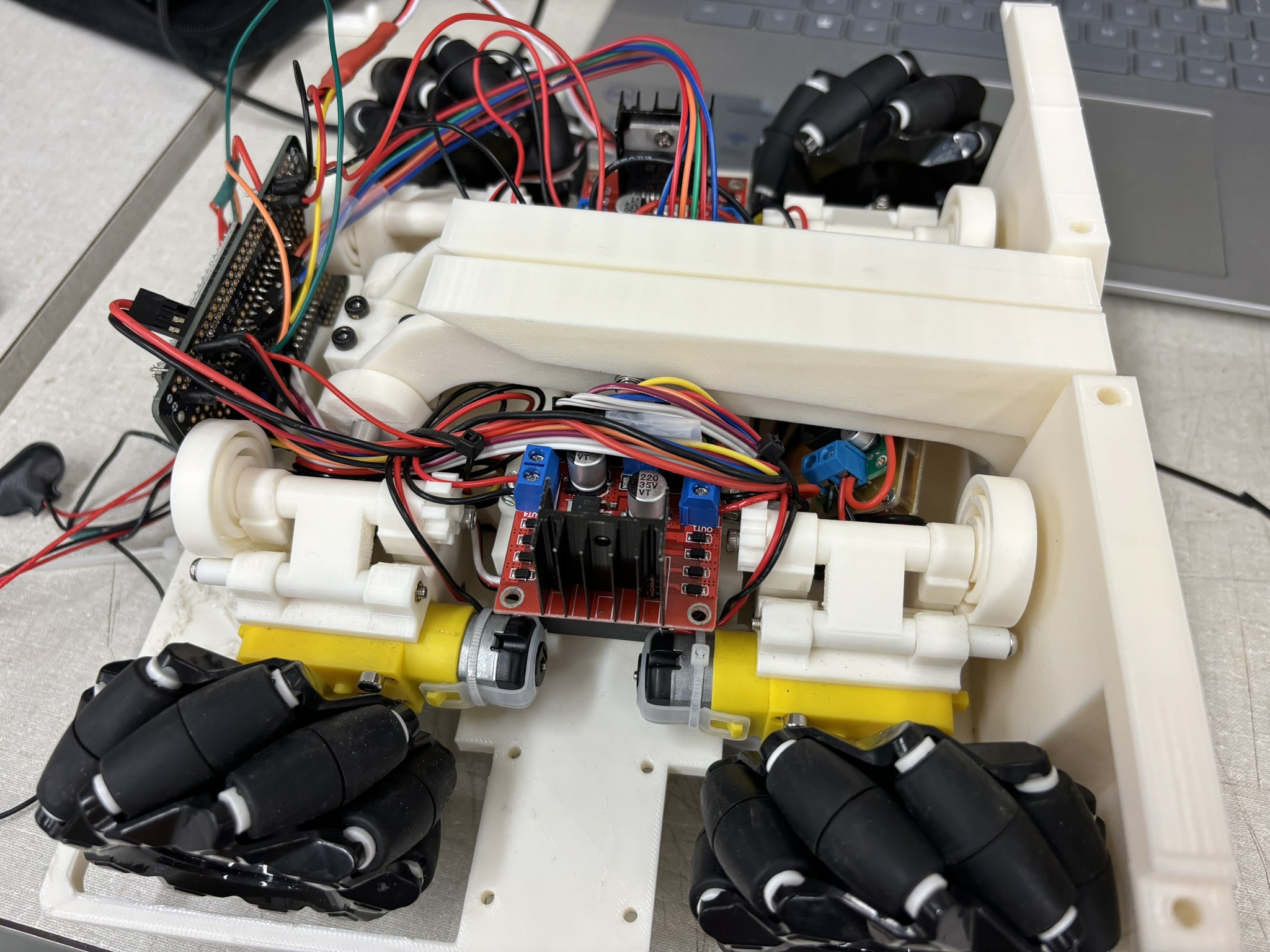
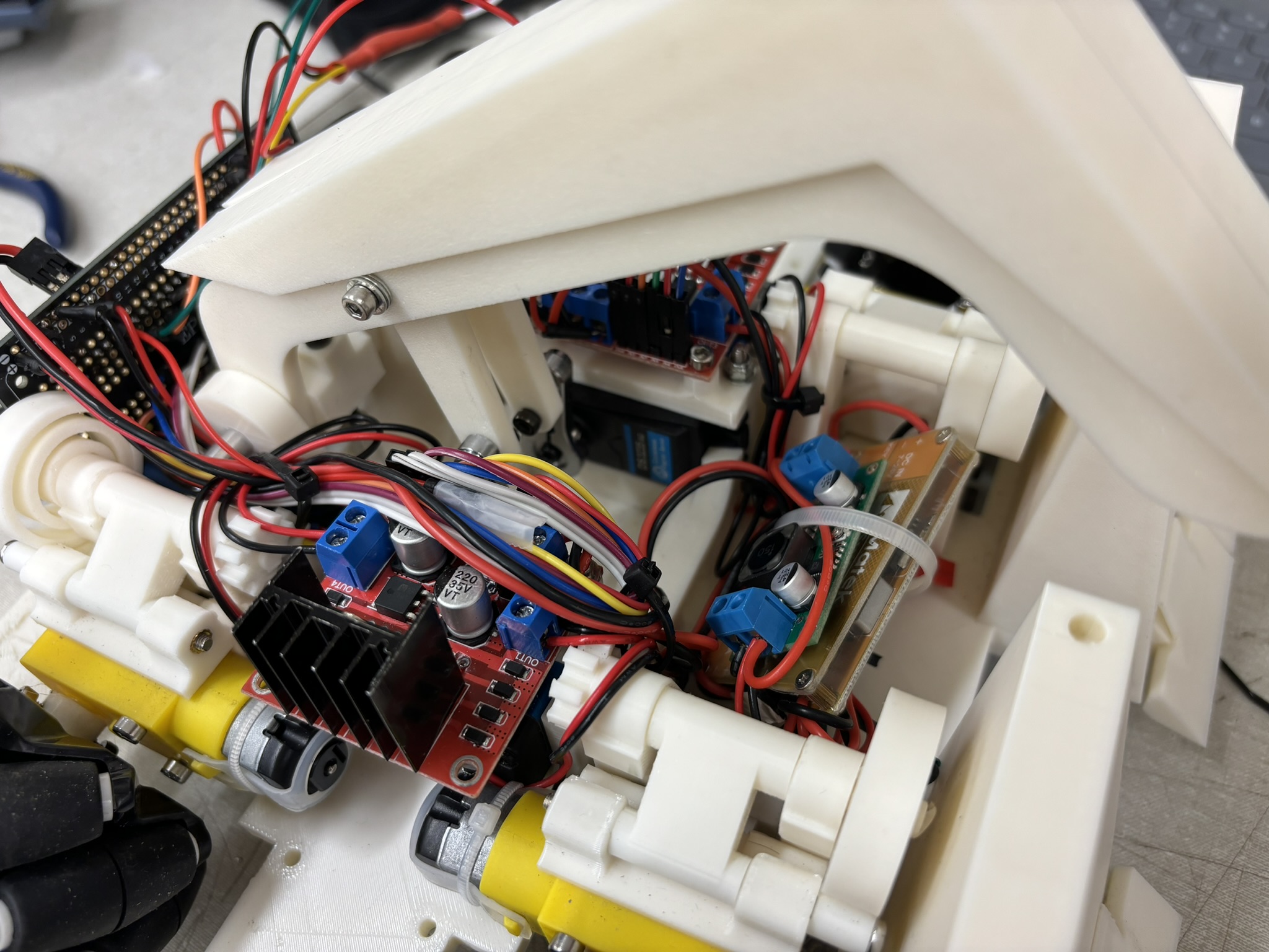
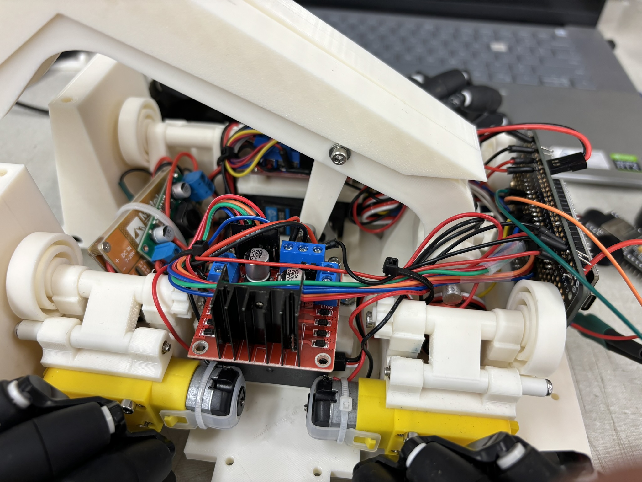
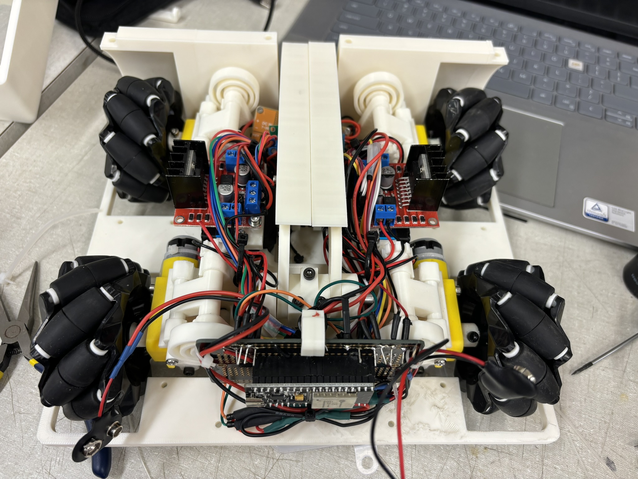
After making sure everything works, it’s time to organize the wires. I designed loops, channels, and space for the wires before the parts were printed.
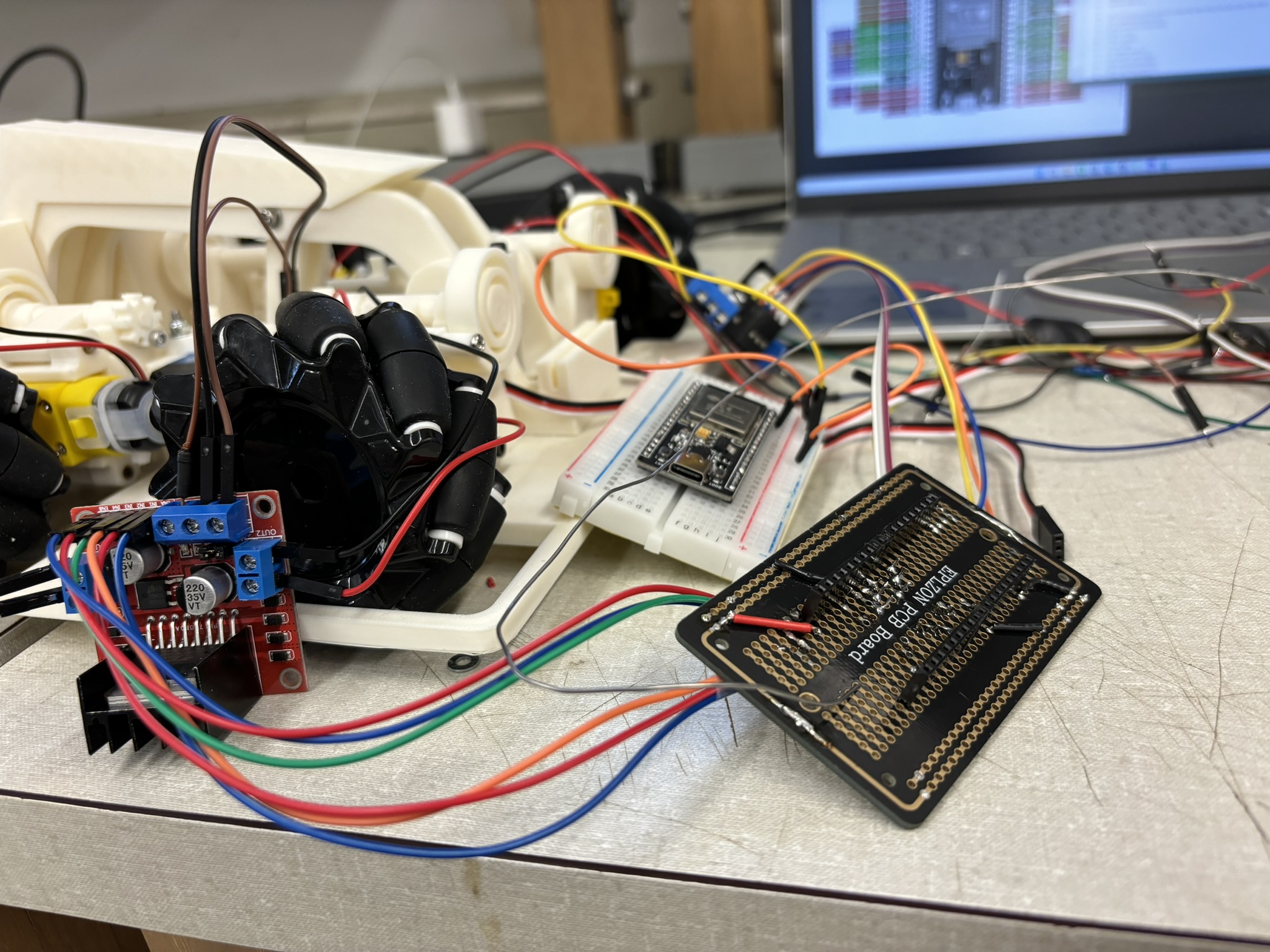
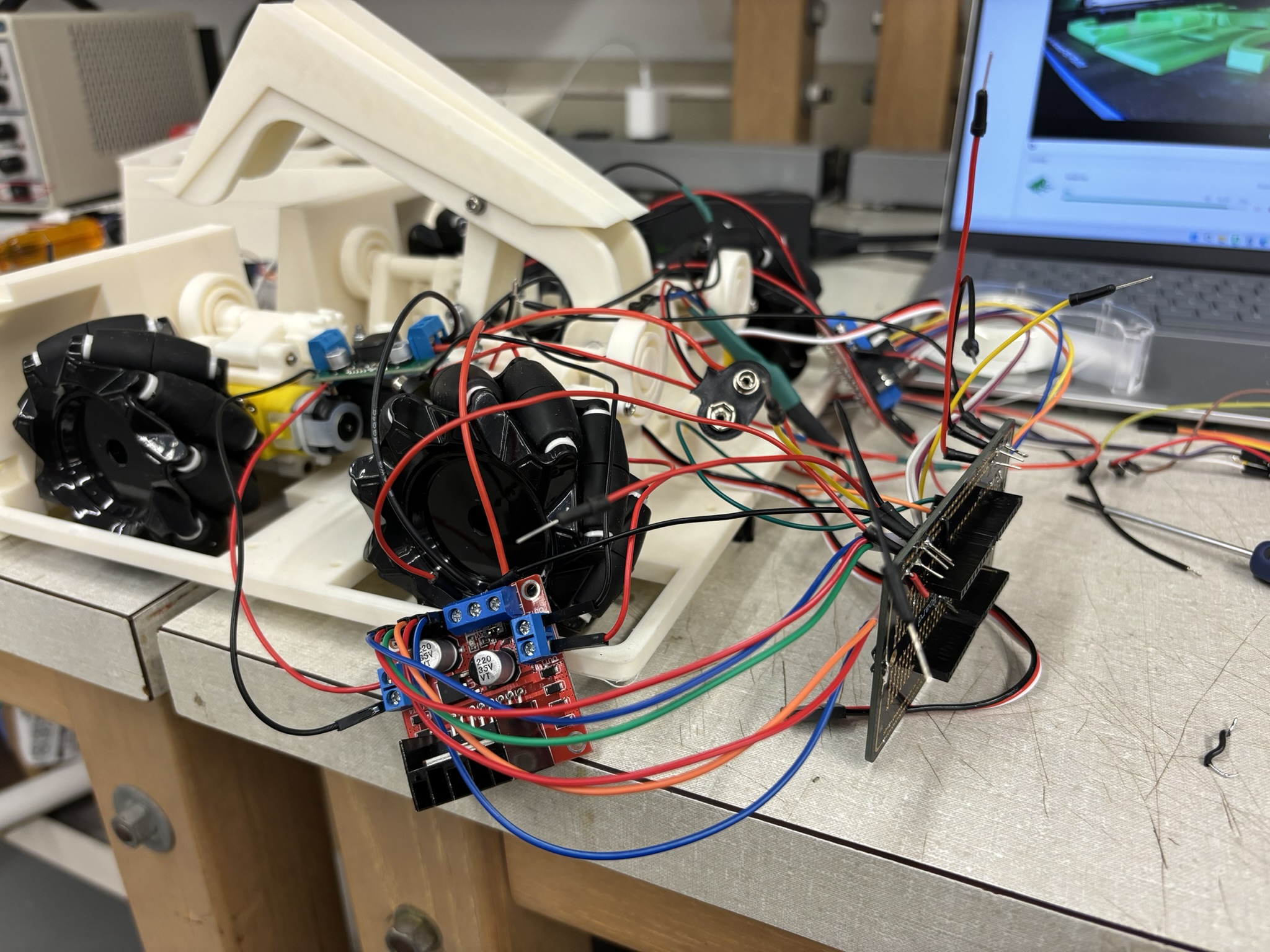
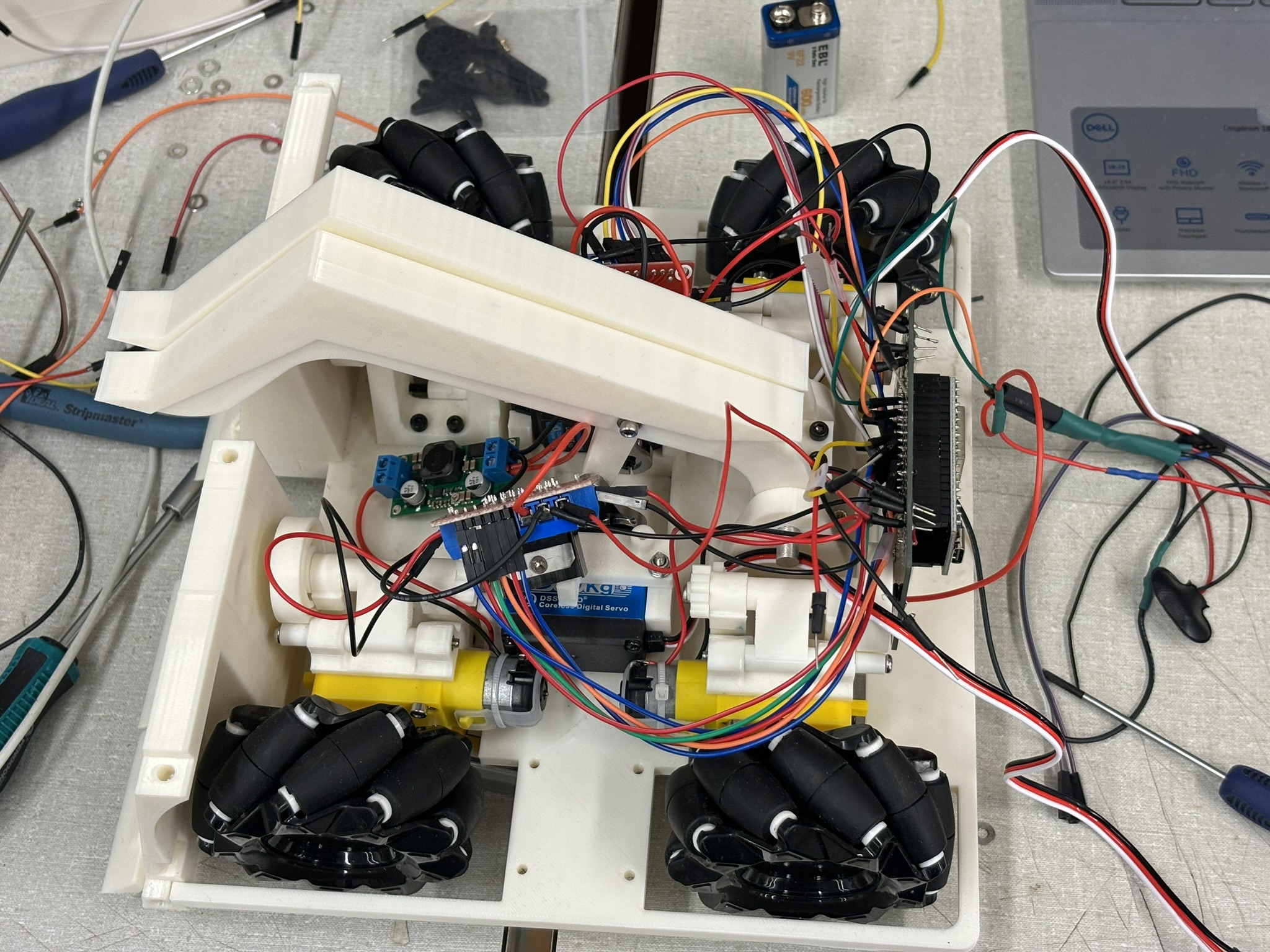
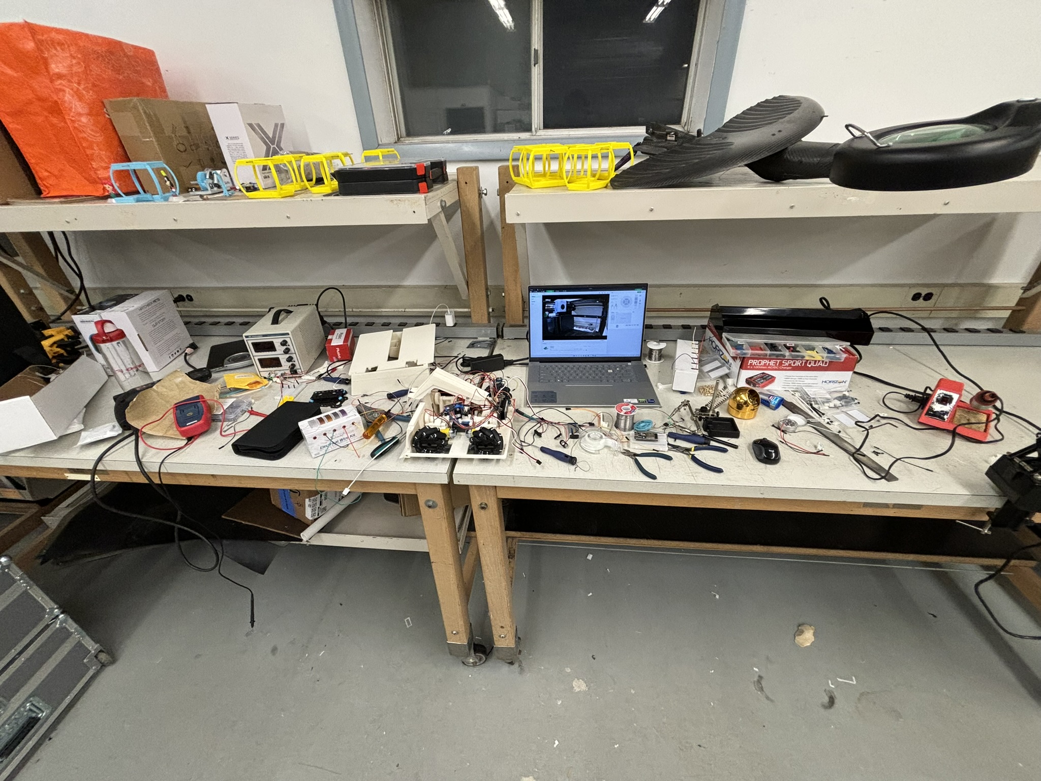
The following video is testing the control after transfer the wires from the breadboard to solderable breadboard. At 00:43, the wheel suddenly stopped and blue LED started flashing because ESP32 restarted by itself. At this moment, I was not using the BEC and connecting the servo into the circuit yet, it’s just 5V from LM298N.
3. Control
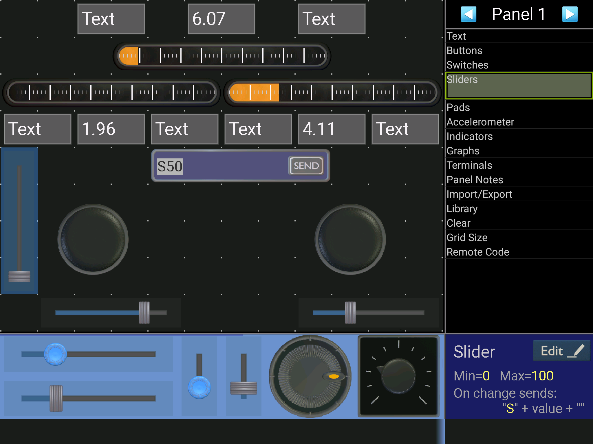
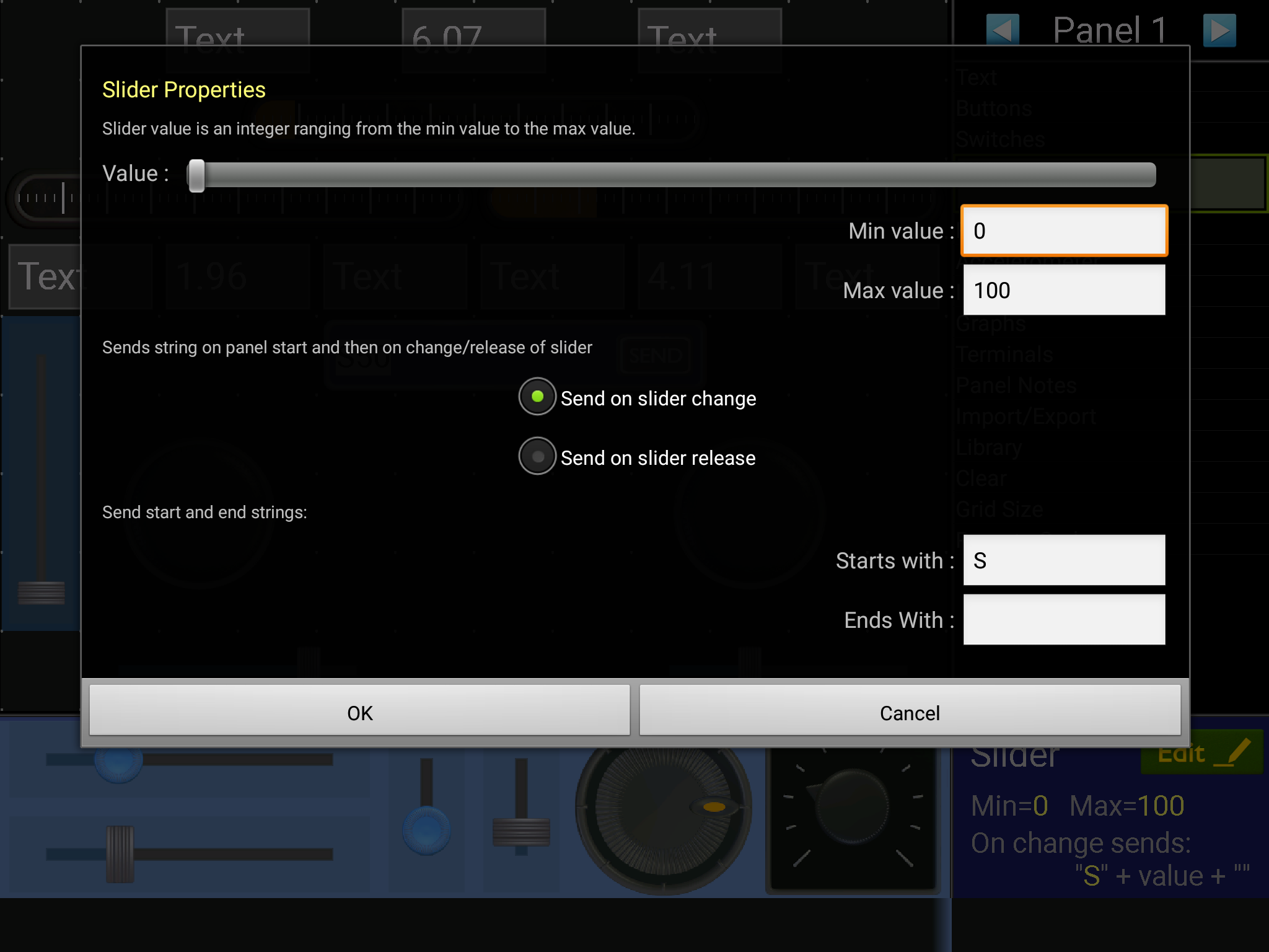
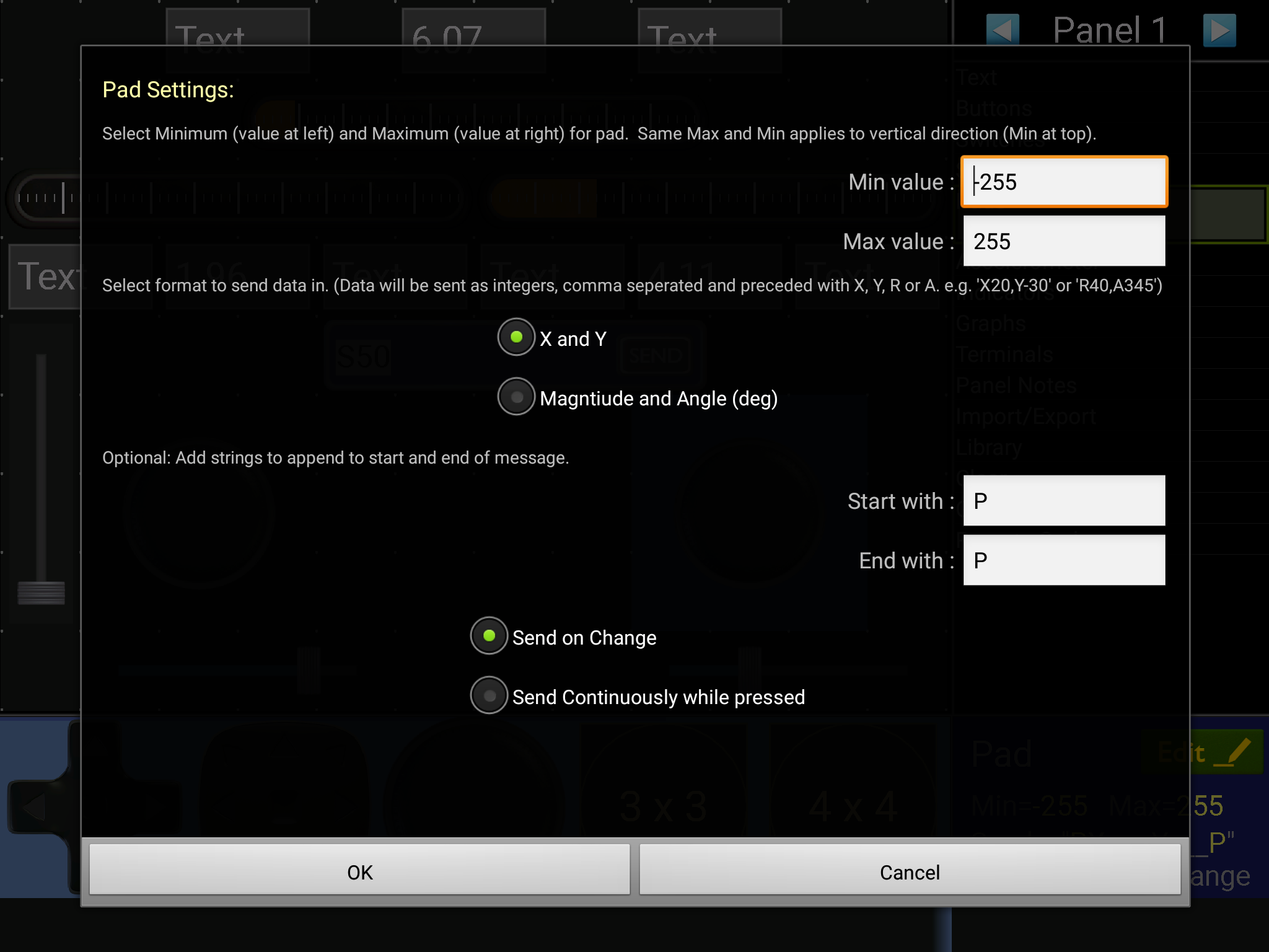
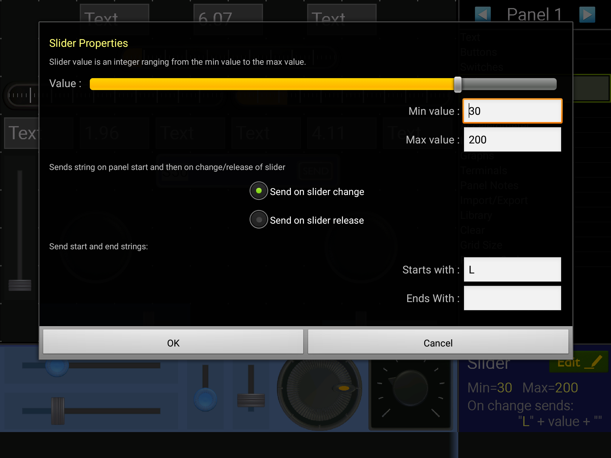
3.1. Bluetooth Serial Communication Setup
Serial communication uses “code” to communicate. It will take the letter or integers and delete it so the next character can come in.
3.2. Improvement of joystick on a smooth surface
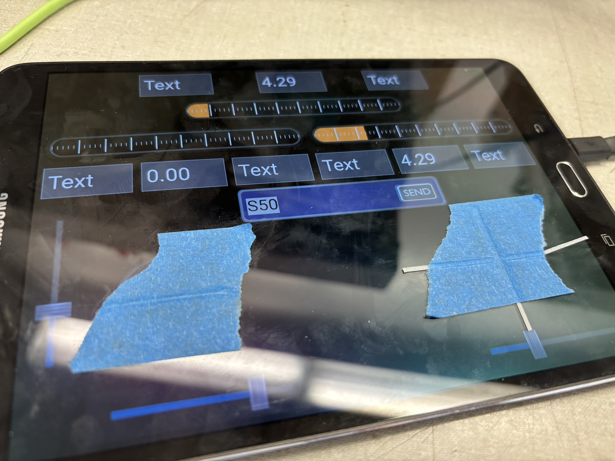
Unlike physical joysticks, you can’t really feel it, so I taped two 3D printed line on it. Physical joysticks have precise forward-backward motion because you need some extra amount of force to go side ways. I also added dead zone in the code, so it won’t output if the input is below 50. More detail is in the code. The orange bar didn’t work well, so I would just read the numeric value and it’s totally enough.
4. Code
#include "BluetoothSerial.h"

#if !defined(CONFIG_BT_ENABLED) || !defined(CONFIG_BLUEDROID_ENABLED)
#error Bluetooth is not enabled! Please run `make menuconfig` to and enable it
#endif

BluetoothSerial SerialBT;

//#include <WiFi.h>
//#include <WiFiClient.h>

#include <ESP32Servo.h>
////////////////////////////////////////// Motors //////////////////////////////////////////
#define M1A 26
#define M1B 25
#define M1P 33

#define M2A 19
#define M2B 18
#define M2P 21

#define M3A 5
#define M3B 17
#define M3P 16

#define M4A 27
#define M4B 14
#define M4P 12

int M_pin[12]={M1A,M1B,M1P,M2A,M2B,M2P,M3A,M3B,M3P,M4A,M4B,M4P};
int Speed[4]={0,0,0,0};
int buffer[4]={0,0,0,0};
float roll;
float pitch;
float yaw;
int yaw_sen=80;
int pitch_roll_sen;

#define S1_pin 32
#define S2_pin 23
Servo S1; // left
Servo S2; // right
int angle_perc;
const float S1_max=126;
const float S1_min=46;
const float S1_range=S1_max-S1_min;
const float S2_max=142;
const float S2_min=60;
const float S2_range=S2_max-S2_min;
////////////////////////////////////////// Motors //////////////////////////////////////////
////////////////////////////////////////// Voltage Monitor //////////////////////////////////////////
#define V1_pin 36
#define V_tot_pin 39
#define R1 10 // Mohms
#define R2 1 // Mohms
#define voltage_constant 3.3/4095*(R1+R2)/R2
// Vb=3.3x/4095*(R1+R2)/R2=voltage_constant*x
float Vb1;
float Vb2;
float Vb_tot;

const float Vb1_max=8.22;
const float Vb1_min=7.5;
const float Vb1_range=Vb1_max-Vb1_min;

const float Vb2_max=8.22;
const float Vb2_min=7.5;
const float Vb2_range=Vb1_max-Vb1_min;

float Vb_tot_max=Vb1_max+Vb2_max;
float Vb_tot_min=Vb1_min+Vb2_min;
float Vb_tot_range=Vb_tot_max-Vb_tot_min;
////////////////////////////////////////// Voltage Monitor //////////////////////////////////////////
////////////////////////////////////////// Bluetooth //////////////////////////////////////////
int update_interval=100; // time interval in ms for updating panel indicators
unsigned long last_time=0; // time of last update
char data_in; // data received from serial link
//String text; // String for text elements
int progress; // Progress Bar Value
////////////////////////////////////////// Bluetooth //////////////////////////////////////////
void setup() {
  pinMode(2,OUTPUT);
  Serial.begin(115200);
  SerialBT.begin(115200);
  build_panel();

  digitalWrite(2,HIGH); delay(100); digitalWrite(2,LOW); delay(100);
  digitalWrite(2,HIGH); delay(100); digitalWrite(2,LOW); delay(100);
  delay(400);

  digitalWrite(2,HIGH); delay(100); digitalWrite(2,LOW); delay(100);
  digitalWrite(2,HIGH); delay(100); digitalWrite(2,LOW); delay(100);
  delay(400);
  // for (int i=0;1<12;i++){
  //   pinMode(M_pin[i],OUTPUT);
  //   Serial.println(M_pin[i]);
  //   digitalWrite(2,HIGH); delay(1000); digitalWrite(2,LOW); delay(20);
  // }
  pinMode(M1A,OUTPUT); pinMode(M1B,OUTPUT); pinMode(M1P,OUTPUT); Serial.println("M1 done.");
  pinMode(M2A,OUTPUT); pinMode(M2B,OUTPUT); pinMode(M2P,OUTPUT); Serial.println("M2 done.");
  pinMode(M3A,OUTPUT); pinMode(M3B,OUTPUT); pinMode(M3P,OUTPUT); Serial.println("M3 done.");
  pinMode(M4A,OUTPUT); pinMode(M4B,OUTPUT); pinMode(M4P,OUTPUT); Serial.println("M4 done.");

  digitalWrite(2,HIGH); delay(100); digitalWrite(2,LOW); delay(100);
  digitalWrite(2,HIGH); delay(100); digitalWrite(2,LOW); delay(100);
  delay(400);

  Serial.println("start servo");
  // digitalWrite(2,HIGH); delay(200); digitalWrite(2,LOW); delay(200);
  // digitalWrite(2,HIGH); delay(200); digitalWrite(2,LOW); delay(200);
  // delay(1000);

  S1.setPeriodHertz(50);
  S2.setPeriodHertz(50);
  S1.attach(S1_pin);
  S2.attach(S2_pin);

  Serial.println("servo attach done.");

  digitalWrite(2,HIGH); delay(100); digitalWrite(2,LOW); delay(100);
  digitalWrite(2,HIGH); delay(100); digitalWrite(2,LOW); delay(100);
  digitalWrite(2,HIGH); delay(100); digitalWrite(2,LOW); delay(100);
  digitalWrite(2,HIGH); delay(100); digitalWrite(2,LOW); delay(100);
  delay(400);
}

void loop() {
  receive_data();
  speed_calculation();
  motor_output();
  voltage_monitor();
  send_data();

  Serial.println();
}

void speed_calculation(){
  if (roll>-50 && roll<50 && pitch!=0){
    roll=0;
  } else if (pitch>-50 && pitch<50 && roll!=0){
    pitch=0;
  }
  // Serial.print(float(pitch_roll_sen)/100);Serial.print("\t");
  // Serial.print(float(yaw_sen)/100);Serial.print("\t");
  float mpitch=pitch*float(pitch_roll_sen)/100;
  float mroll=roll*float(pitch_roll_sen)/100;
  float myaw=yaw*float(yaw_sen)/100;
  // Serial.print(mroll);Serial.print("\t");
  // Serial.print(mpitch);Serial.print("\t");
  // Serial.print(myaw);Serial.print("\t");
  buffer[0]=mpitch+mroll+myaw;
  buffer[1]=mpitch-mroll-myaw;
  buffer[2]=mpitch+mroll-myaw;
  buffer[3]=mpitch-mroll+myaw;
  // Serial.print(buffer[0]);Serial.print("\t");
  // Serial.print(buffer[1]);Serial.print("\t");
  // Serial.print(buffer[2]);Serial.print("\t");
  // Serial.print(buffer[3]);Serial.print("\t");

  int buffer_max=0;
  for (int i=0;i<3;i++){
    if (abs(buffer[i])>=abs(buffer[i+1])){
      buffer_max=buffer[i];
    }
  }
  //Serial.print(buffer_max);Serial.print("\t");

  if (abs(buffer_max)>255){
    float proportion=abs(255/float(buffer_max));
    //Serial.print(proportion);Serial.print("\t");
    Speed[0]=buffer[0]*proportion;
    Speed[1]=-buffer[1]*proportion;
    Speed[2]=buffer[2]*proportion;
    Speed[3]=-buffer[3]*proportion;

  } else {
    Speed[0]=buffer[0];
    Speed[1]=-buffer[1];
    Speed[2]=buffer[2];
    Speed[3]=-buffer[3];
    //Serial.print("prop NA");Serial.print("\t");
  }

  Serial.print(Speed[0]);Serial.print("\t");
  Serial.print(Speed[1]);Serial.print("\t");
  Serial.print(Speed[2]);Serial.print("\t");
  Serial.print(Speed[3]);Serial.print("\t");
  Serial.print("|\t");

}

void motor_output(){

  if (Speed[0]>=0){
    digitalWrite(M1A, HIGH);
    digitalWrite(M1B, LOW);
    analogWrite(M1P, abs(Speed[0]));
  } else if  (Speed[0]<0) {
    digitalWrite(M1B, HIGH);
    digitalWrite(M1A, LOW);
    analogWrite(M1P, abs(Speed[0]));
  }

  if (Speed[1]>=0){
    digitalWrite(M2A, HIGH);
    digitalWrite(M2B, LOW);
    analogWrite(M2P, abs(Speed[1]));
  } else if  (Speed[1]<0) {
    digitalWrite(M2B, HIGH);
    digitalWrite(M2A, LOW);
    analogWrite(M2P, abs(Speed[1]));
  }

  if (Speed[2]>=0){
    digitalWrite(M3A, LOW);
    digitalWrite(M3B, HIGH);
    analogWrite(M3P, abs(Speed[2]));
  } else if  (Speed[2]<0) {
    digitalWrite(M3B, LOW);
    digitalWrite(M3A, HIGH);
    analogWrite(M3P, abs(Speed[2]));
  }

 if (Speed[3]>=0){
    digitalWrite(M4A, HIGH);
    digitalWrite(M4B, LOW);
    analogWrite(M4P, abs(Speed[3]));
  } else if  (Speed[3]<0) {
    digitalWrite(M4B, HIGH);
    digitalWrite(M4A, LOW);
    analogWrite(M4P, abs(Speed[3]));
  }

  int S1_angle=S1_min+float(angle_perc)/100*S1_range;
  int S2_angle=S2_max-float(angle_perc)/100*S2_range;

  if (S1_angle > S1_max){
    S1_angle=S1_max;
  } else if (S1_angle<S1_min){
    S1_angle=S1_min;
  }
  if (S2_angle>S2_max){
    S2_angle=S2_max;
  } else if (S2_angle<S2_min){
    S2_angle=S2_min;
  }
  S1.write(S1_angle);
  S2.write(S2_angle);
  //if (angle >20)digitalWrite(2,HIGH); else digitalWrite(2,LOW);
  // Serial.print(angle_perc);Serial.print("\t");
  // Serial.print(S1_angle);Serial.print("\t");
  // Serial.print(S2_angle);Serial.print("\t");
}

void voltage_monitor(){
  int x1=analogRead(V1_pin);
  Vb1=voltage_constant*x1;

  int x_tot=analogRead(V_tot_pin);
  Vb_tot=voltage_constant*x_tot;

  Vb2=Vb_tot-Vb1;
}


void build_panel(){
  // Build panel in app
  SerialBT.println("*.kwl");
  SerialBT.println("clear_panel()");
  SerialBT.println("set_grid_size(12,9)");
  SerialBT.println("add_text_box(5,0,2,L,Text,245,240,245,H)");

  SerialBT.println("add_text_box(10,3,2,L,Text,245,240,245,)");
  SerialBT.println("add_text_box(4,3,2,L,Text,245,240,245,)");
  SerialBT.println("add_text_box(6,3,2,L,Text,245,240,245,)");
  SerialBT.println("add_text_box(0,3,2,L,Text,245,240,245,)");
  SerialBT.println("add_text_box(2,0,2,L,Text,245,240,245,)");
  SerialBT.println("add_text_box(8,0,2,L,Text,245,240,245,)");

  SerialBT.println("add_text_box(2,3,2,L,Text,245,240,245,F)");
  SerialBT.println("add_text_box(8,3,2,L,Text,245,240,245,G)");
  SerialBT.println("add_slider(1,9,3,0,100,0,A,A,0)");
  SerialBT.println("add_slider(1,8,2,0,100,0,L,L,0)");
  SerialBT.println("add_slider(8,8,2,0,100,0,R,R,0)");
  SerialBT.println("add_slider(0,5,4,0,40,0,S,S,0)");
  SerialBT.println("add_free_pad(2,5,-255,255,0,0,Y,)");
  SerialBT.println("add_free_pad(8,5,-255,255,0,0,R,P)");
  SerialBT.println("add_gauge(6,2,4,0,100,50,g,,,10,5)");
  SerialBT.println("add_gauge(0,2,4,0,100,0,f,,,10,5)");
  SerialBT.println("add_gauge(3,1,4,0,100,0,h,,,10,5)");
  SerialBT.println("set_panel_notes(-,,,)");
  SerialBT.println("run()");
  SerialBT.println("*");
}

void receive_data(){
  if (SerialBT.available()){
    //digitalWrite(2,HIGH);
    data_in=SerialBT.read();  //Get next character

    if(data_in=='L'){ //  Slider
      yaw_sen=SerialBT.parseInt();
    }

    if(data_in=='R'){ //  Slider
      pitch_roll_sen=SerialBT.parseInt();
    }

    if(data_in=='S'){ // Servo
      angle_perc=SerialBT.parseInt();
    }

    // Left joy, yaw
    if(data_in=='W'){ //  yaw
      while(true){
        if (SerialBT.available()){
          data_in=SerialBT.read();  //Get next character
          if(data_in=='X') yaw=SerialBT.parseInt();
          if(data_in=='W') break; // exit loop
        }
      }
    }

    // Right joy, roll and pitch
    if(data_in=='P'){ //  Pad Start Text
      while(true){
        if (SerialBT.available()){
          data_in=SerialBT.read();  //Get next character
          if(data_in=='X') roll=SerialBT.parseInt();
          if(data_in=='Y') pitch=-SerialBT.parseInt();
          if(data_in=='P') break; // End character
        }
      }
    }

  } //else {
  //   digitalWrite(2,LOW);
  //   yaw = yaw_previous;
  //   roll = roll_previous;
  //   pitch = pitch_previous;
  // }
}

void send_data(){
  unsigned long t=millis();
  if ((t-last_time)>update_interval){
    last_time=t;

    SerialBT.print("*F"+String(Vb1)+"*");
    SerialBT.print("*G"+String(Vb2)+"*");
    SerialBT.print("*H"+String(Vb_tot)+"*");

    // Orange Progress Bar (Range is from 0 to 100)
    progress=(Vb1-Vb1_min)/Vb1_range*100;
    SerialBT.print("*f"+String(progress)+"*");

    progress=(Vb2-Vb2_min)/Vb2_range*100;;
    SerialBT.print("*g"+String(progress)+"*");

    progress=(Vb_tot-Vb_tot_min)/Vb_tot_range*100;
    SerialBT.print("*h"+String(progress)+"*");
  }
}
5. Test Drives
The first test drives include power test, control test, ramp test.
This is the endurance test with fully assembled robot and two fully charged battery. I was also practicing the control with adjustable sensitivity. The whole video is 18 minutes long, and the remaining batteries were around 7.6V. So if I am using flipper very often and pushing it at full throttle at the same time, the time would be much shorter. For the one battery racing condition, using flipper and full throttle at the same time will trigger current overflow protection.
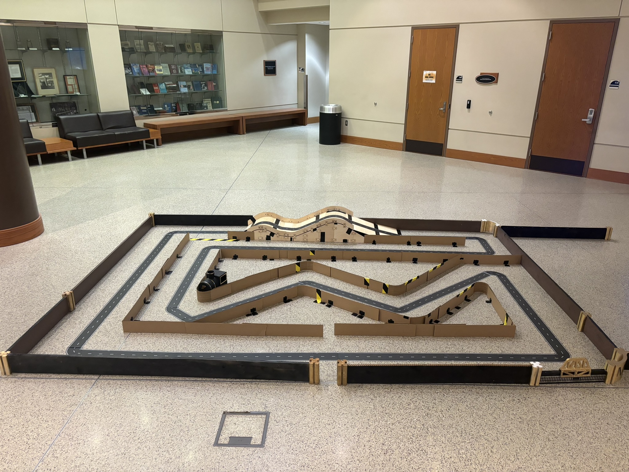
Then I was practicing on the racing track. I could control it and let it run through the S curves very smoothly without touching the walls, but that’s rare and it’s not captured by the camera. The time recorded by Prof. Liu was about 49 seconds with some slip-ups.
6. The Final Battle
The day has come!
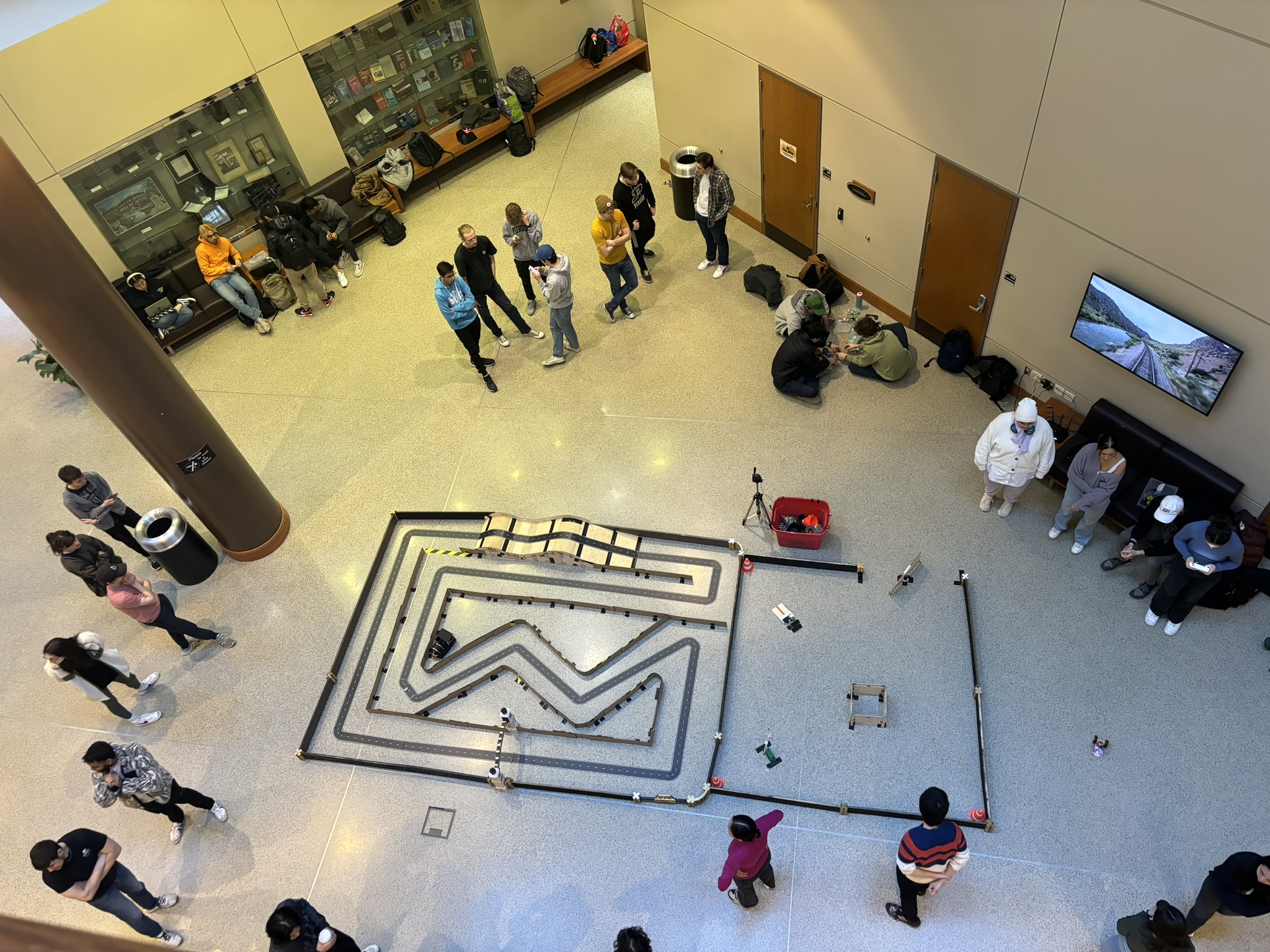
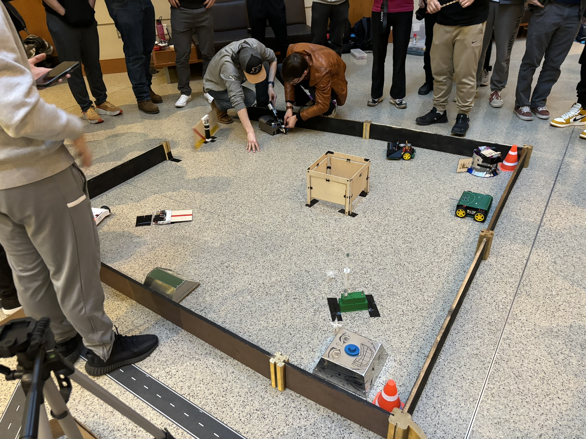
6.1. Performance Analysis
I apologize that my girlfriend blocked the live stream camera for a while, so I also put the video filmed by her.
I joined the battle of the first section, but Prof. Liu took it out in the middle of the battle and banned me for the rest of three lab sections. Before the finale began, she said “don’t be so aggressive at the beginning”, so I was moving it around very slowly just making sure I don’t get stuck.
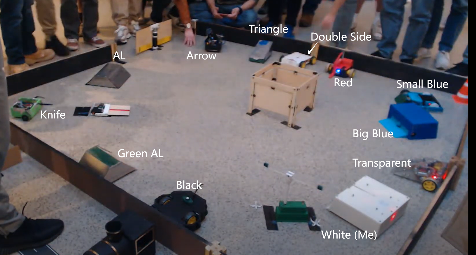
I just give each one a nick name so it’s easier for me to describe what’s happening.
- White: it’s me
- Transparent: It has two wheels and a flipper in the front.
- Big Blue: it’s blue. The ramp in the front can rotate.
- Small Blue: it’s also blue, but smaller. It has reduction gear, high friction wheels, metal frame.
- Red: it’s red. It has a spring loaded flipper.
- Double Side: it can run on both sides. That’s annoying.
- Triangle: it looks like a triangle. Or I should call it cheese.
- Arrow: it has compressed air tank on it and should be able to push a piston and shoot the arrow out. But that one didn’t work.
- AL: it has fully covered aluminum armor.
- Knife: they taped a table knife in the front and two forks on the side.
- Green AL: it also has fully covered aluminum armor, but with green paint on the top
- Black: it’s black, and it has a servo arm in the front wiping left and right.
- 2:15:55: battle started
- 2:16:08: Transparent started attacking me, then I ran away.
- 2:16:32: AL attacked Black hard.
- 2:16:42: Red tried to flip Double Side, but it didn’t work out very well.
- 2:17:04: Green AL tried to attacked me, so I turned and used the front armor to defense. The slope worked very well and got under it easily.
- 2:17:06: Transparent pushed Double Side near the trap, and Small Blue pushed it sideways so Double Side is aligned with the trap door.
- 2:17:13: Double Side is OUT.
- 2:17:52: AL gave Arrow a final push, and Arrow get stuck by the trap.
- 2:18:03: Arrow is OUT.
- 2:18:19: White attacked Big Blue in the front, but it just lifted the flipper and didn’t do any damage. Then Big Blue turned around, I guess it’s defensing from AL, so I attacked again from the butt. Still I can’t flip it over.
- 2:19:22: Transparent showed its butt to me so I went full throttle and attack it. All the movement before that is below half throttle. Again, if the flipper is also pushing forward it would be a kill.
- 2:19:57: Big Blue was showing his butt again, so I attacked. Small Blue was also pushing it behind me, and AL was blocking in the front. Sorry my girlfriend blocked the camera. You can watch the video below at 4:12
- 2:20:19: Big Blue is OUT, but no one took it out until
- 4:32 (video below): I attacked Knife from the back several times, but it’s at the wall and I couldn’t really use speed to flip over.
- 4:34 (video below): Green AL is OUT.
- 2:21:03: AL tried to corner me, but I lift it so it lost the traction and fight back
- 2:21:21: I attacked Transparent again, but still couldn’t KO with that speed. Then I was still trying to save the battery.
- 2:21:54: AL pushed Triangle to the flipper, and Triangle got stuck and just stood there.
- 2:22:18: Transparent was running into the trap, so I tried to push it in. Still couldn’t flip over.
- 2:22:31: Triangle is OUT.
- 2:22:36: I saw Knife is near the gate, so I tried to push it out, but its left wheel got stuck on the wall.
- 2:22:58: I tried to flip Transparent again, but my flipper is just not long enough.
- 2:22:10: Knife is OUT.
- 2:22:22: I tried to kill Black, but White didn’t accelerate to the max speed. It was so close.
- 2:23:40: Black got cornered by AL.
- 2:23:55: Black is OUT.
- 2:24:30: Small Blue ran into my weapon. Attack!
- 2:24:41: Small Blue tried to come out, so I pushed it in again.
- 2:25:01: I wanted to push both of them out of the gate. I should go full speed. I don’t know why I stopped the
- 2:25:12: I pushed them again, and the right wheel of Transparent got pushed by the gate.
- 2:25:17: Transparent is OUT.
- 2:25:21: I tried to lift AL and push it to the gate, but AL fell from my flipper.
- 2:25:25: I didn’t retract the flipper on time, so this time I can’t lift it. Meanwhile, AL is at higher speed, and White was stationary, so I am not sure if White can push against it. If White was pushed to the wall, it would be in danger. So my choice is to use speed advantage to go full reverse, turn, and attack. This is the most dangerous moment of the battle.
- 2:25:43: I could just lift it for 10 seconds and AL would be out, but that’s not fun. So I lift it several times, but I let it go. It’s trying to run away, but that did nothing under the power of top maneuverability. Later on, White lifted AL 7 times and every time I could just KO AL.
- 2:27:14: I lifted AL for the last time, and then Red got under AL as well.
- 2:27:36: AL is OUT. GG.
- 2:27:44: the last one was an easy kill.
- Battle is over, everyone came in, then it’s time to show the full power of White. I don’t need to worry about battery anymore. It’s just for fun.
- 2:29:53: Knife’s knife stabbed under my flipper, and I tried to retract, but it couldn’t, so the current over flowed, and battery shut down by itself.
- 2:33:05: AL tried to attack me from the back, so I turned around in fraction of a second, and lift AL again, again, again, again, again, again, again, ….
- After that, White was just ramming around.
- 2:39:44: they just decided to let me kill Red again.
6.2. Damage
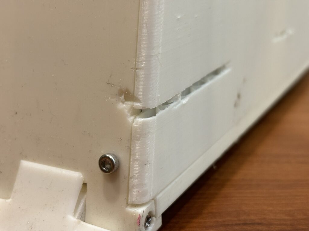
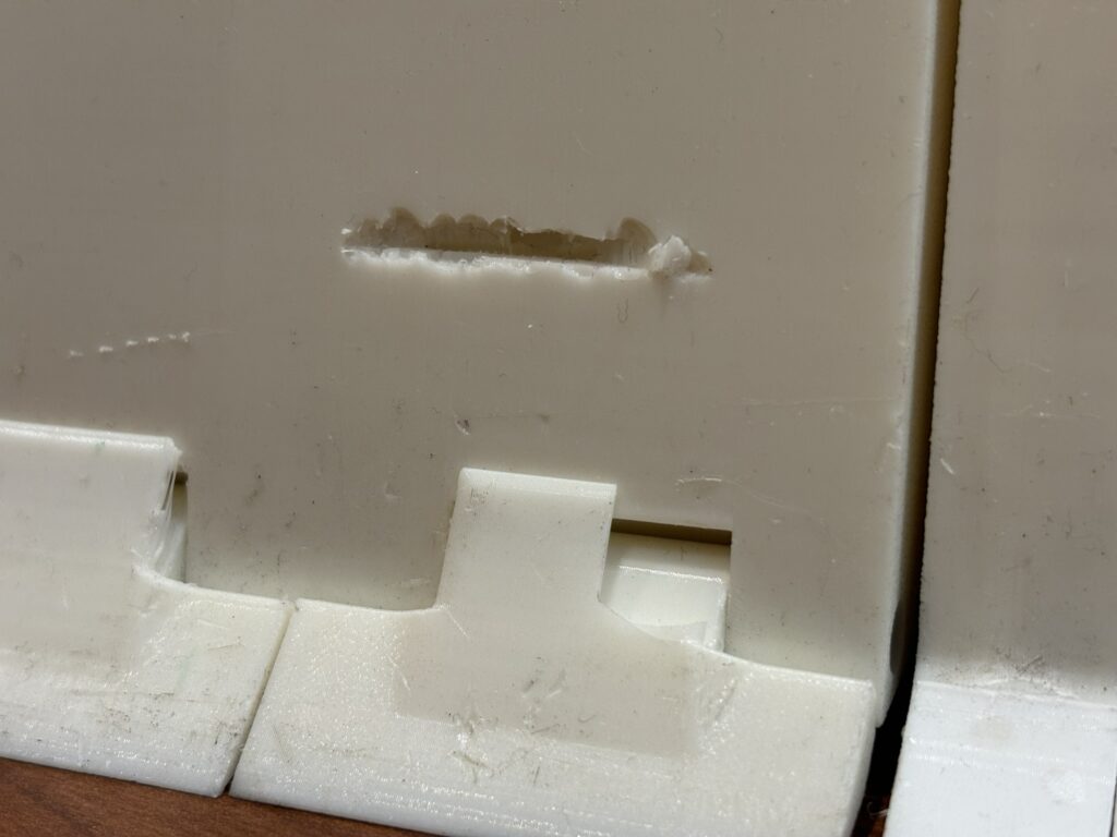
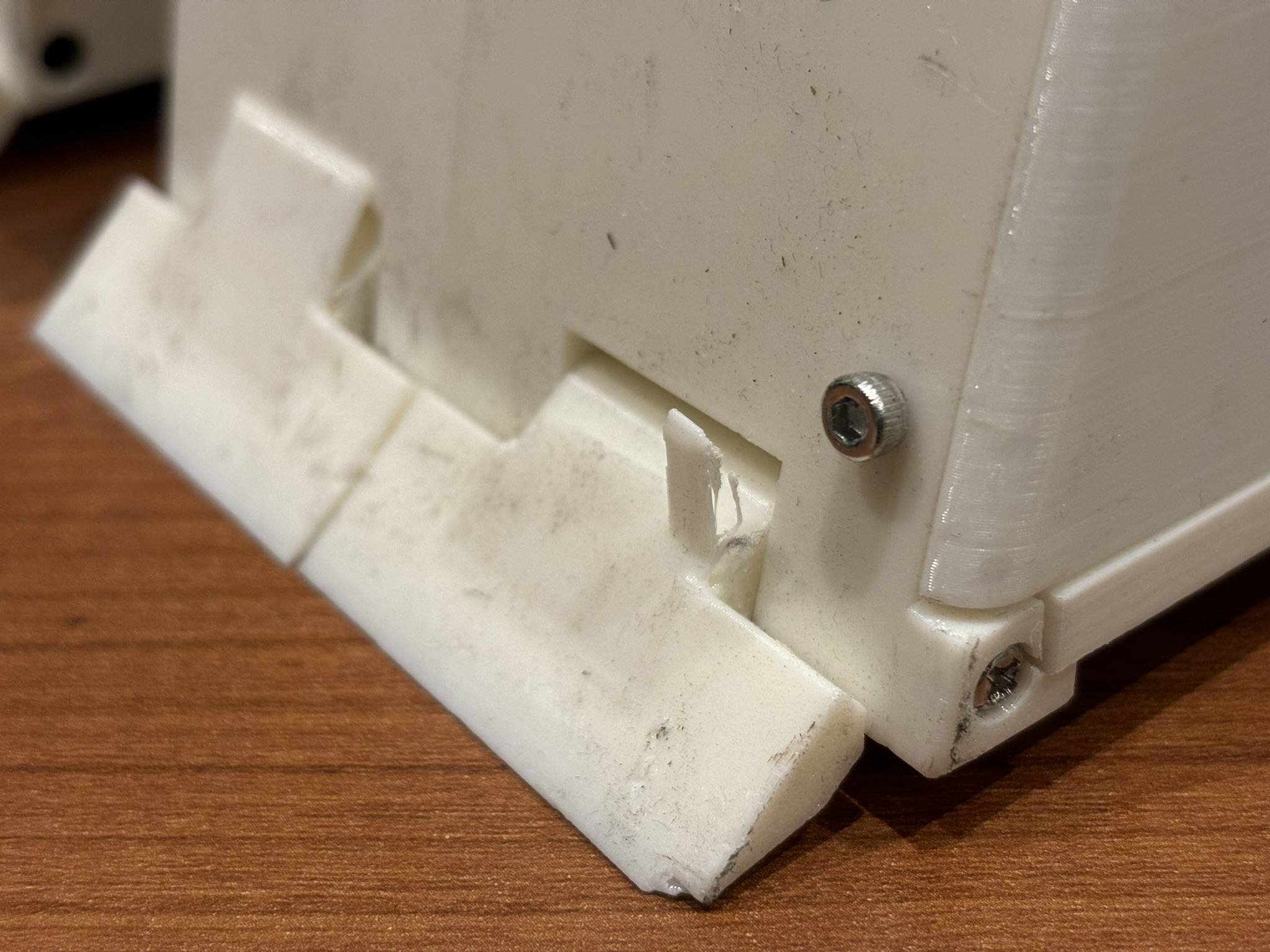
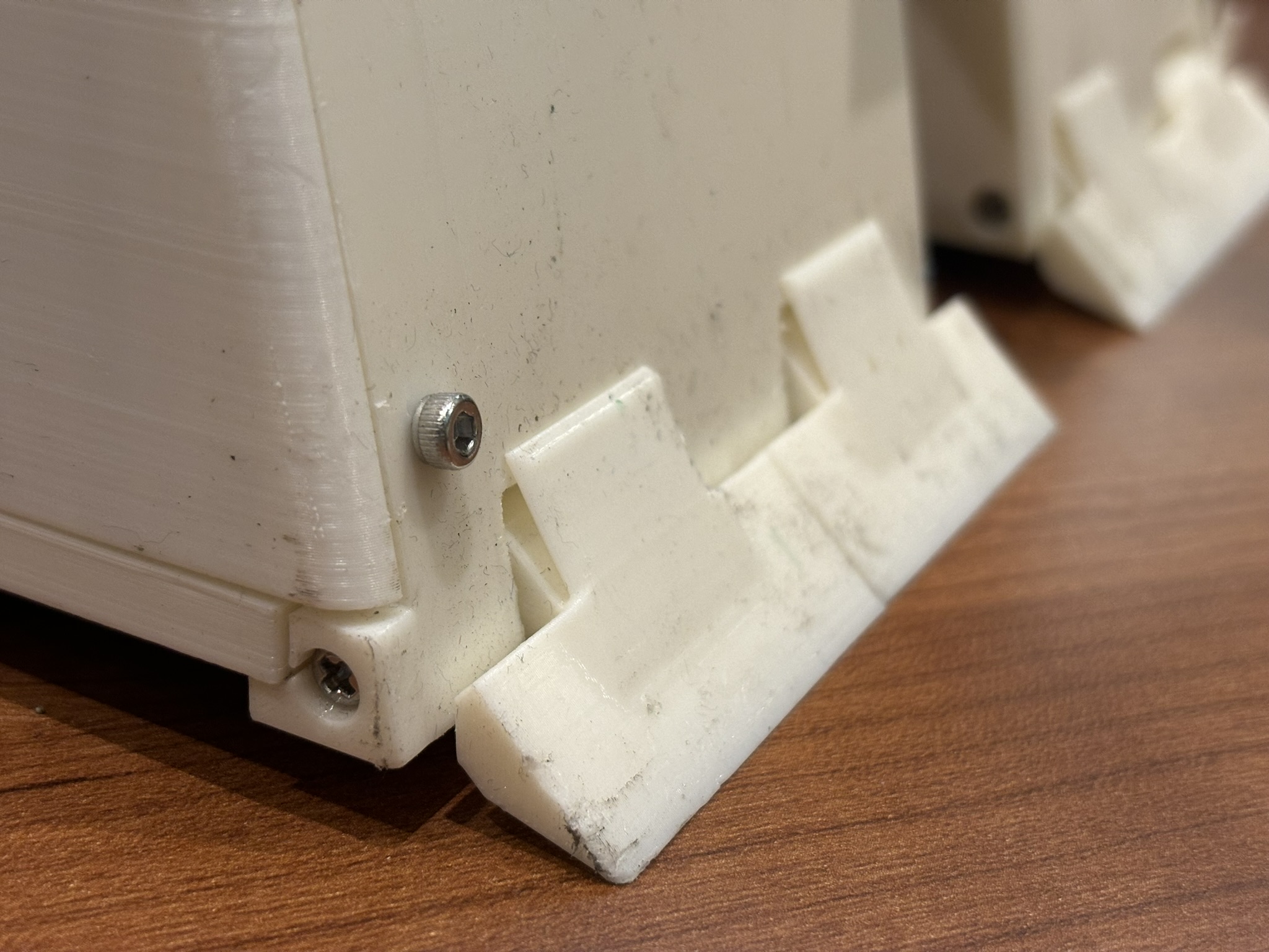
The spring component of the front slope got broken, and there are some dents on the surface. Overall, the armor performs very well. Unfortunately, the compressed air arrow and spinning drum got eliminated so early. I really want to see what’s gonna happen when fighting with them. One team was working on spinning drum but it’s too slow, and for some reason they gave up and didn’t come to the battle.
Another damage was done by the table-knife after the battle. That knife get stuck under the flipper, and I was trying to retract the flipper but it couldn’t, so the servo stalled, current overflowed, and batteries shut down.
7. Reflection
7.1. Suspension
I am so sure that the suspension was pushing the wheel to the ground. The control feels great. No slipping at all. Next time I can try just using suspension on two front wheels to save space.
7.2. Mecanum wheels
I could drive the bot side ways, but I didn’t use it frequently for two reasons. One, I don’t know why it moves very slow when moving sideways even the throttle is already at the max in the racing mode. Two, since the front slop is pushing against the ground during battle, there’s a lot of friction in the front, so it will also change the heading in the opposite direction when moving sideways (but it’s not 100% bad to move in this way). So should I keep the Mecanum wheels? Maybe, I think it will save the life in extreme case.
7.3. Flipper
I was trying to let it move just up and down and pushing it over by the speed advantages, but it’s not high enough so it’s hard to KO the aluminum box during the battle. Of course I can lift it and hold for 10 seconds, but that’s not fun. So, for next flipper design, the flipper need to move very high and also forward.