I. Intro
Date: September – October 2023
If you are a Purdue student and going to build a battle bot for this project, I suggest you read this to the end before you start. I hope this first-hand experience can help you. All the design decisions were iterated for many many times.
SUGGESTION 1: FOCUS ON RACING OR MANEUVERABILITY. If you want to know why, see the rules of battle.
The midterm project for this course was to build a battle bot. The competition was divided into two parts: racing and battle.
Rules for the car: (could change over time)
- Size is within 10”x10”.
- Only one single designated 9V battery can be used.
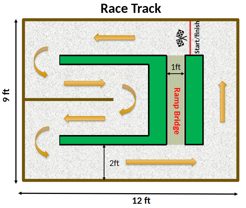
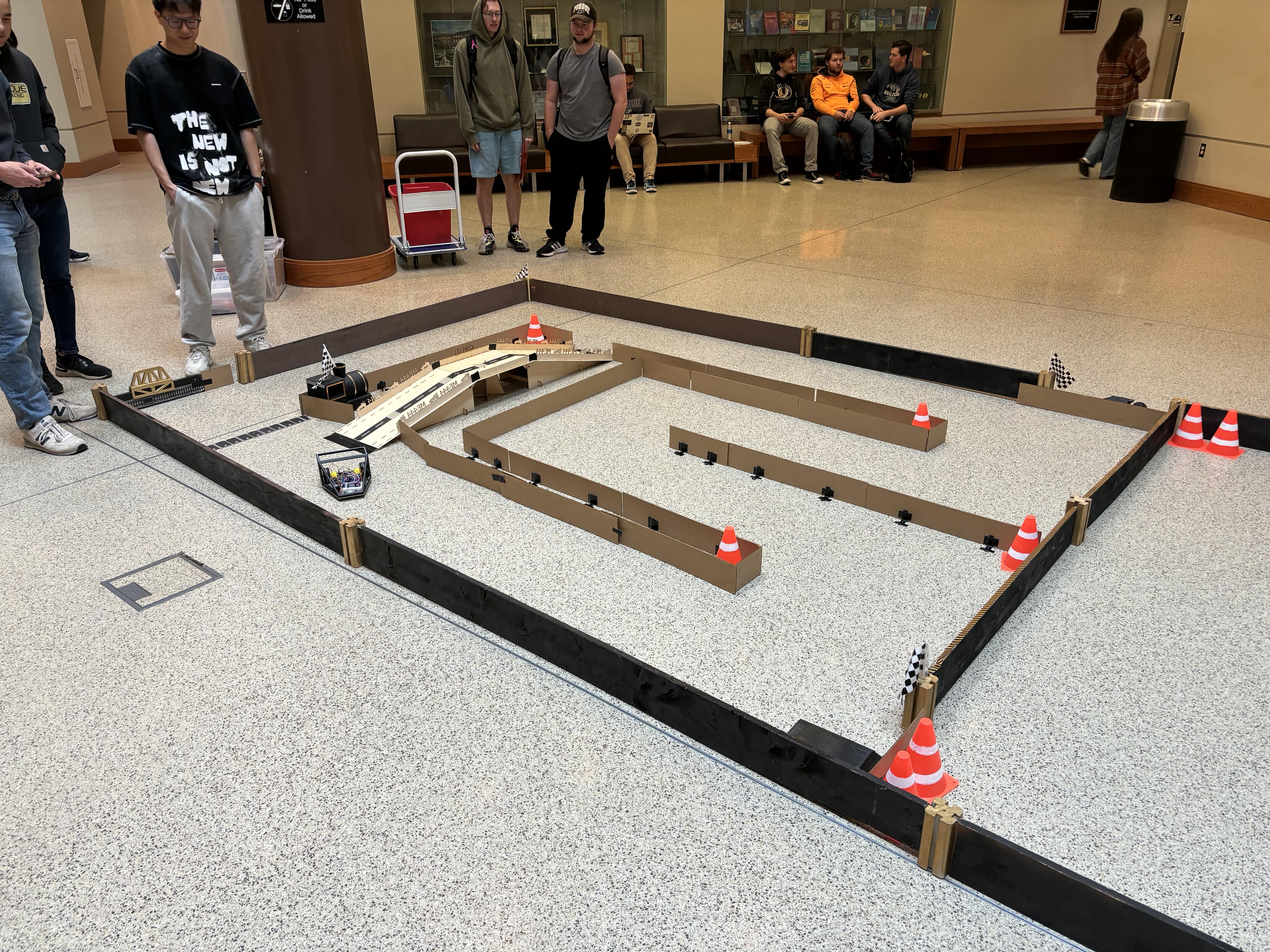
Rules for racing:
- The timer starts when the TA says “GO”
- The timer stops when your butt of the car crosses the line. ATTENTION: The entire car has to cross the line in order to stop the timer.
- After the car crosses the line, you have 30 seconds to cross the bridge. If your car can cross the bridge, there will be a 10-second reduction on your timer.
- The walls are not smooth, there are columns that want to screw you up at all times
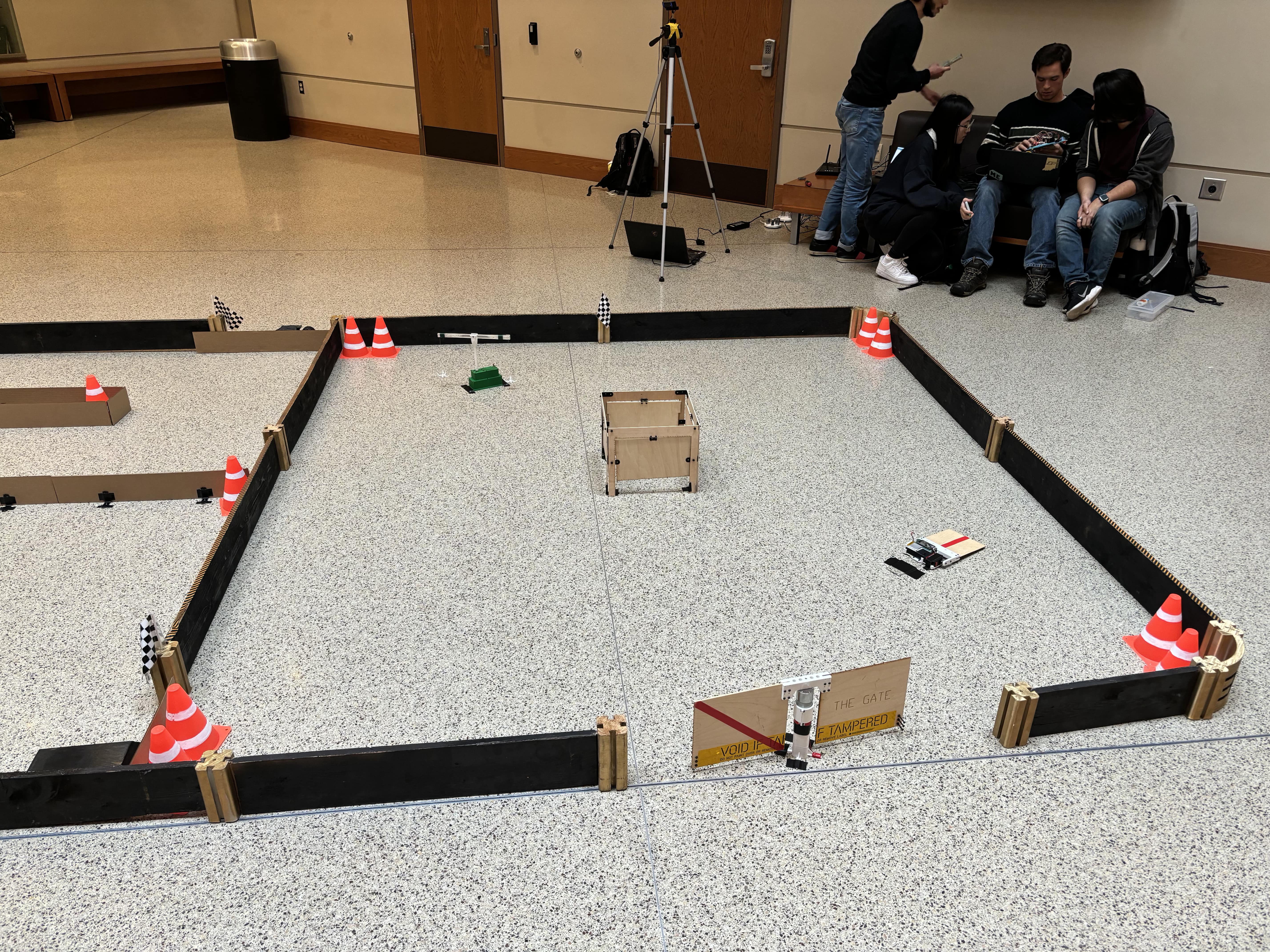
Rules for battle (are just jokes):
- All battle bots from the same lab section will be put into the arena at the same time and compete. (This is DUMB)
- There is no “separate” (This is DUMB) (see next one).
- If you can’t move for 10 seconds, you are out. (This is also DUMB. Example: if botA is pushing botB on the wall, and both are not moving for 10 seconds, botB will be out. But botA is also not moving for 10 seconds, so botA should be out as well. )
- If you are pushed outside, flipped upside-down, or get trapped, out.
II. Design Process
1. Constraints
Our team decided to build a bot that can both do racing and battle, so our bot must:
- have enough clearance to pass the bridge.
- have a large base area enclosed by four wheels
- have enough friction on the driving wheel (VERY IMPORTANT).
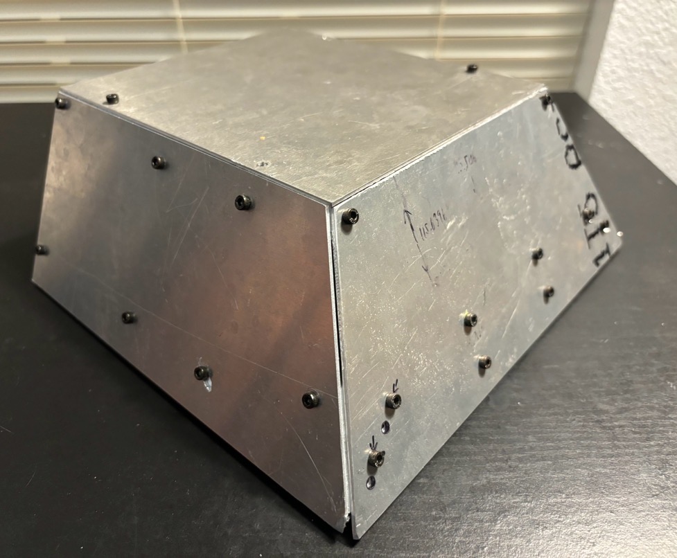
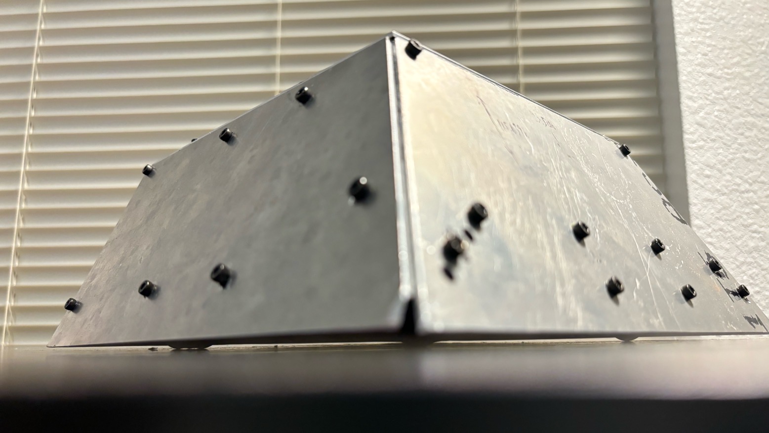
- have sloped metal armor to defend the rotating blade
- install the armor as close to the ground as possible (IT’S BAD, DON’T DO IT)
2. Final Decisions
Based on the constraints above, the following designs were made:
- The bottom height of the chassis was determined by the size of the wheels, the distance between the front wheel and rear wheel, and the simulation in the sketch. The simulation was done by two lines that are 165 degrees (180-15) and tangent to the front and rear wheels.
- The chassis is about 7”x7”
- We made our own wheels by using 2.25” diameter O-rings from Menards. Many O-rings are not even 1” in diameter, so it takes time to actually find it. It’s much better than the yellow hard-rubber wheel provided because it provides more friction.
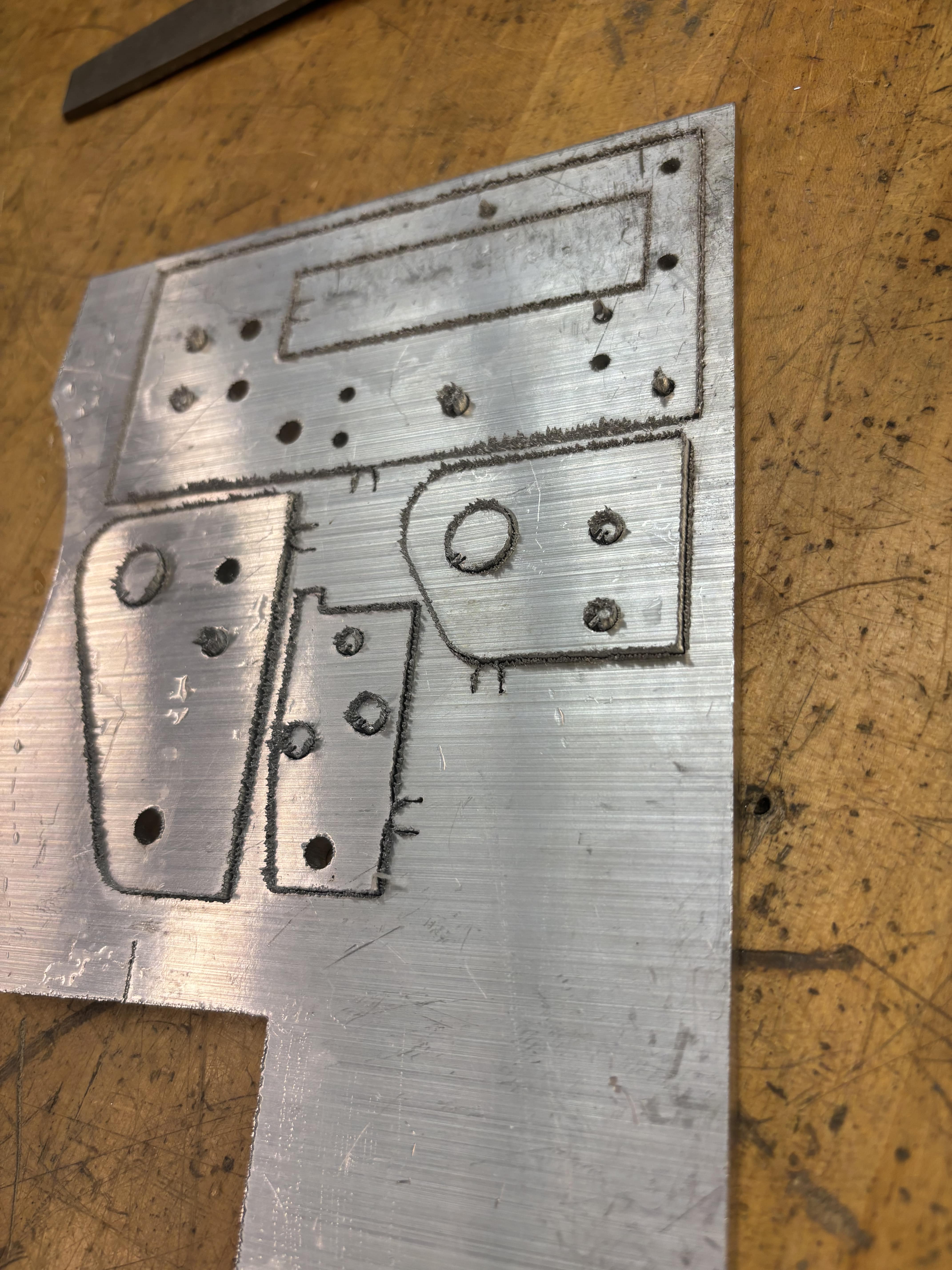
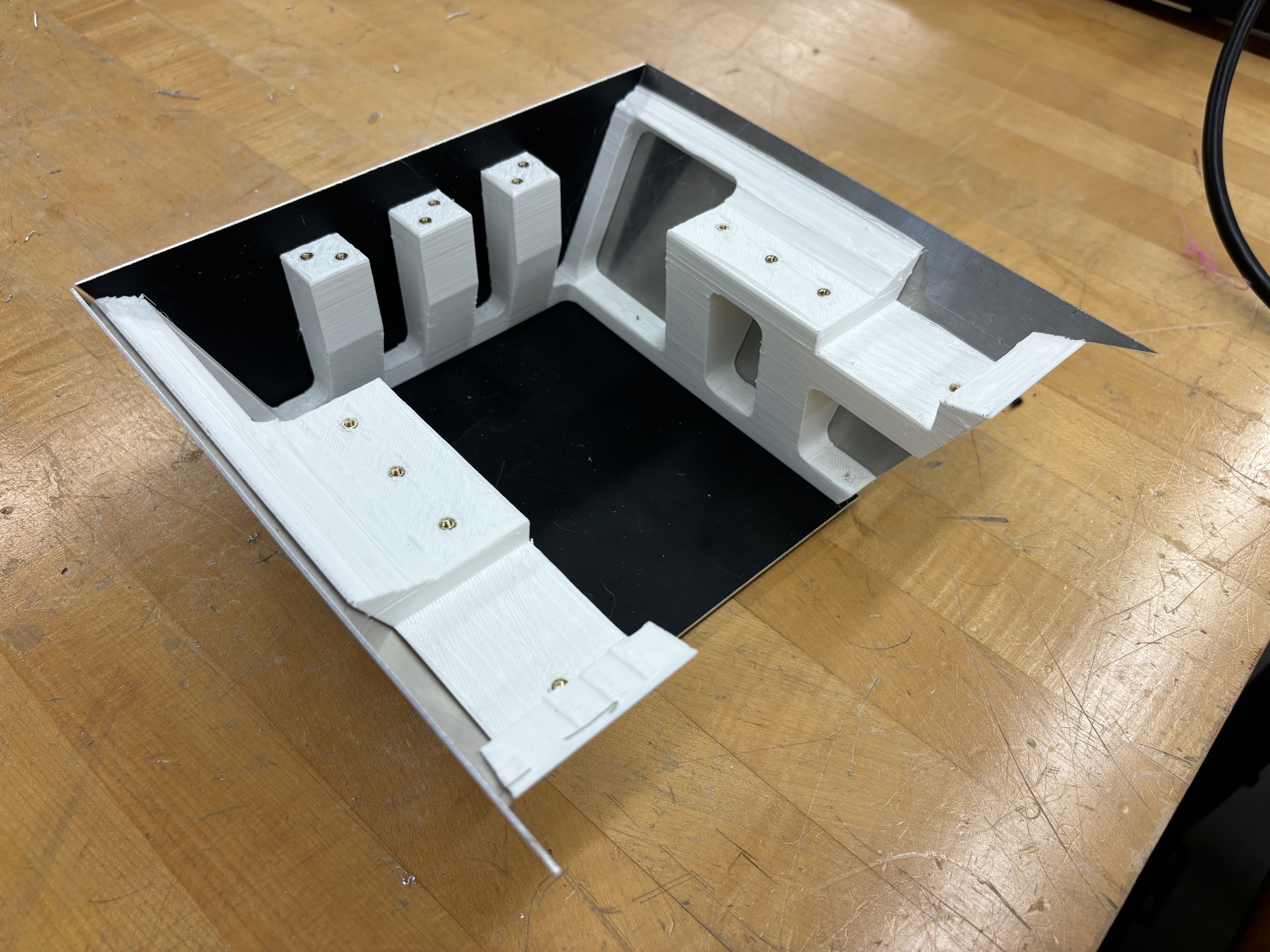
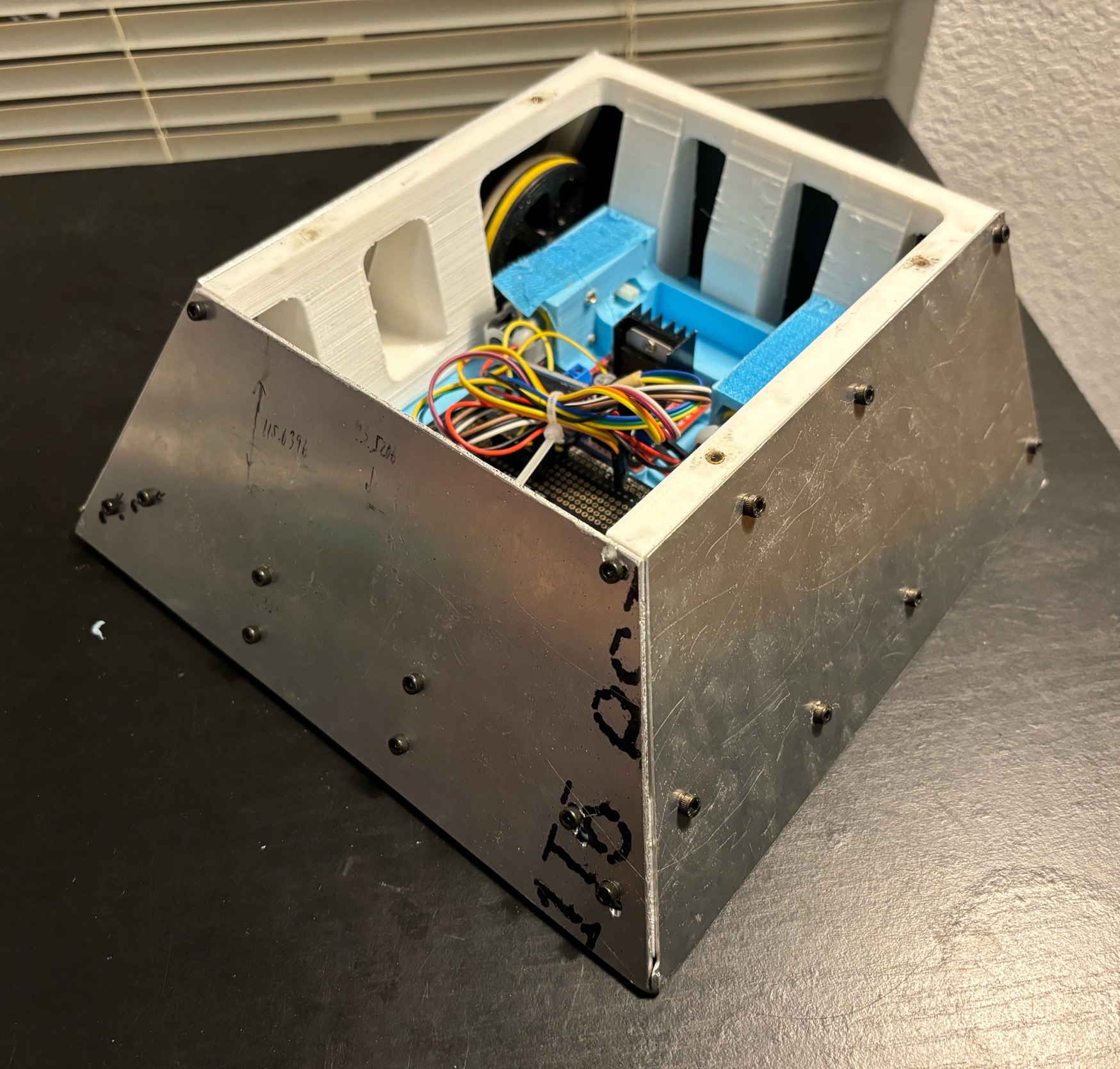
- The sloped armor sheets are made from aluminum sheets (0.04” to 0.1”) and laser cutting. If you want to laser cut the aluminum, I suggest you make the CAD in inches at the beginning because 1. the machine uses inches, 2. PTC Creo can’t convert mm to in properly, and the holes are way off. The sloped armor is designed to protect the front and side. The back is protected by vertical armor due to the wheel size and overall size limit.
- The bot is rare wheel drive, because 1. it went more straight than front wheel drive (we don’t know why), 2. using sloped armor on a large wheel will exceed the size limit and increase the complexity. The two front wheels are metal ball caster wheels from ME375 bot.
- When it’s racing, the armor is not installed, and three lead blocks are put on the back of the car to increase friction. Even though they decreased acceleration, the car became more controllable. When it’s battle time, the lead blocks will be replaced by the armor.
III. Prototypes
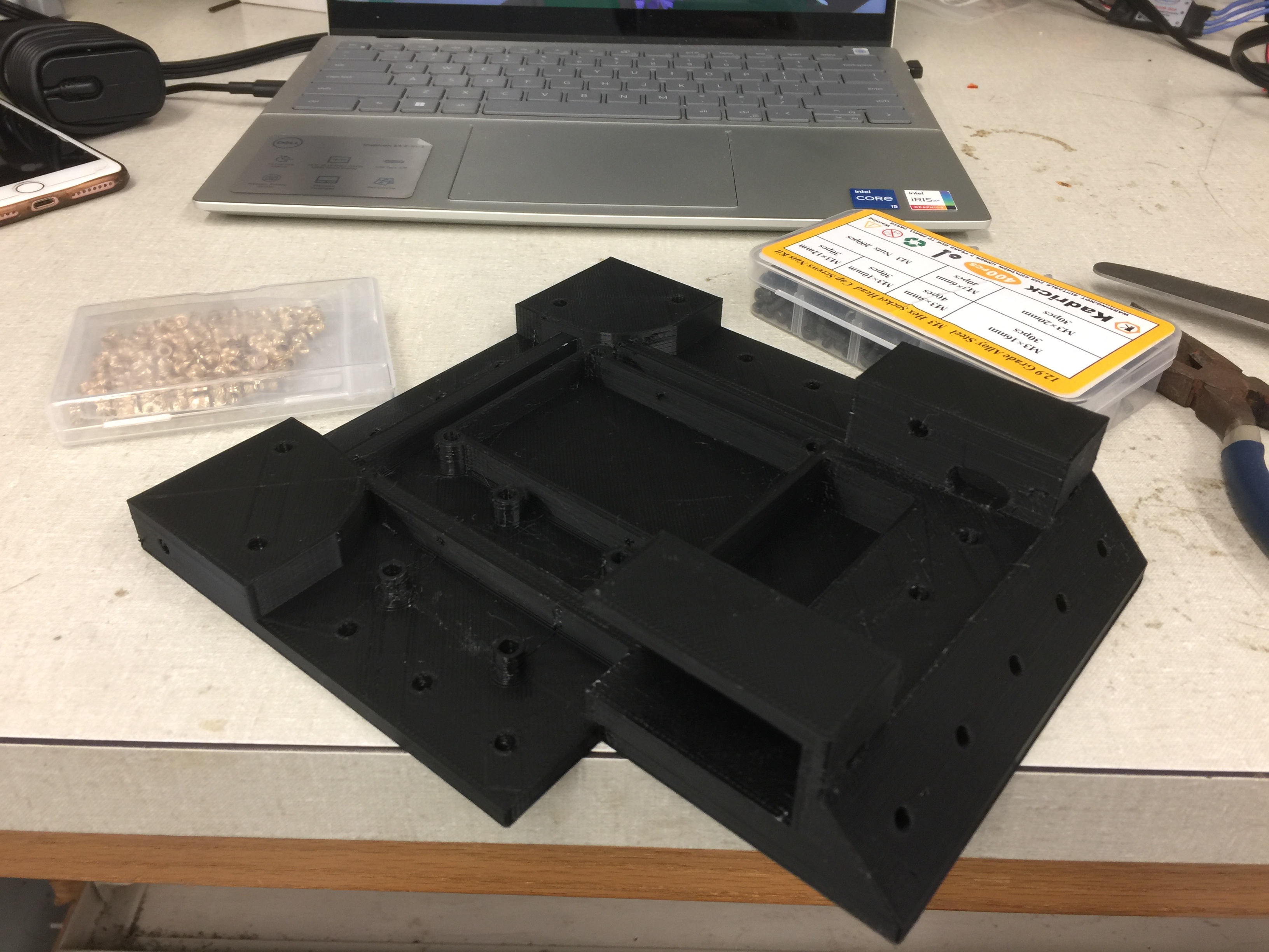
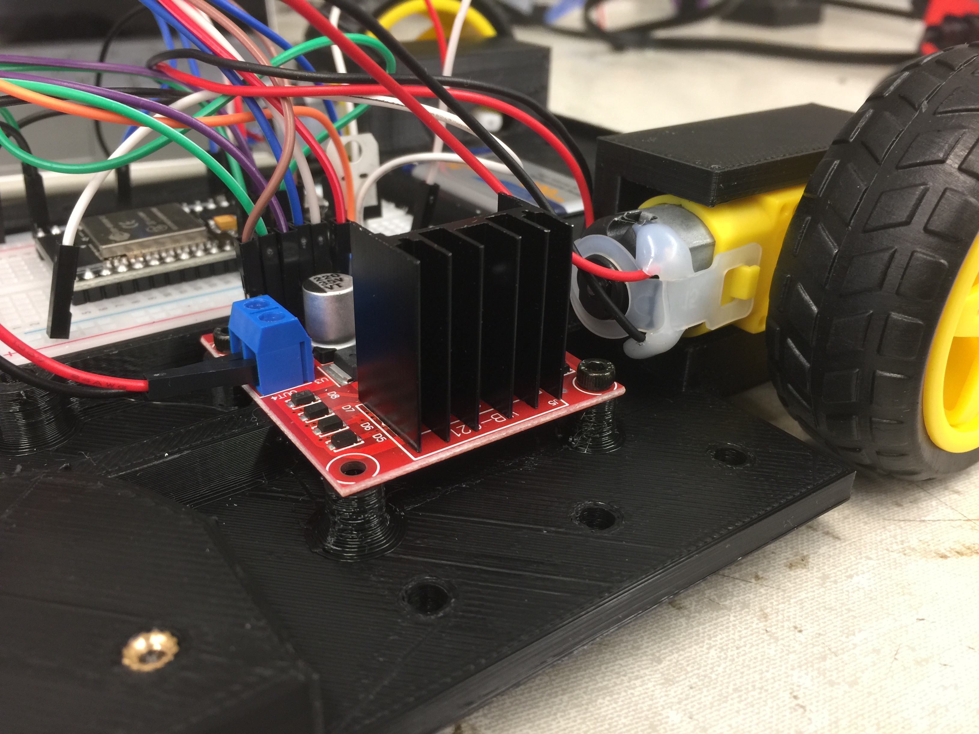
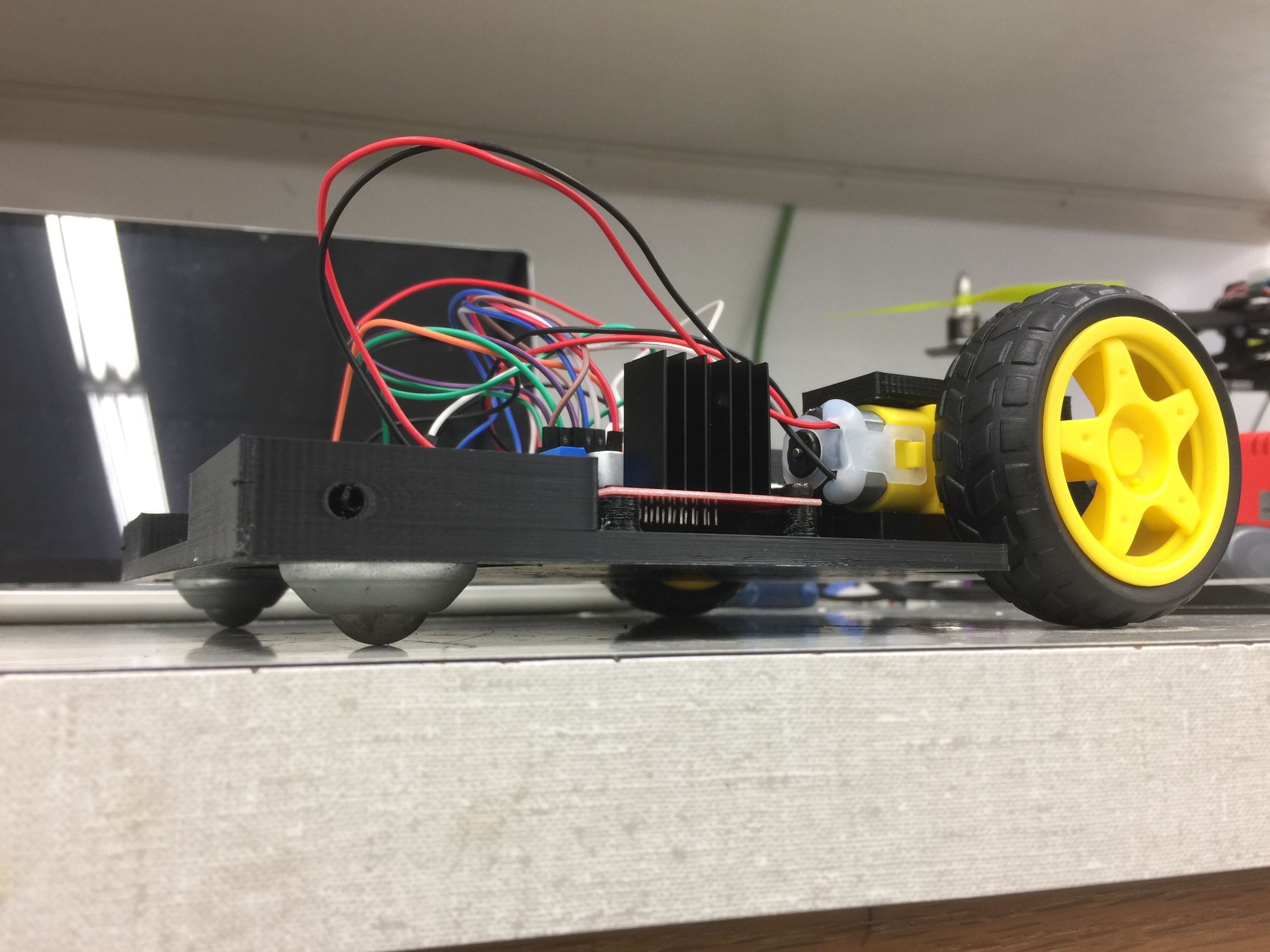
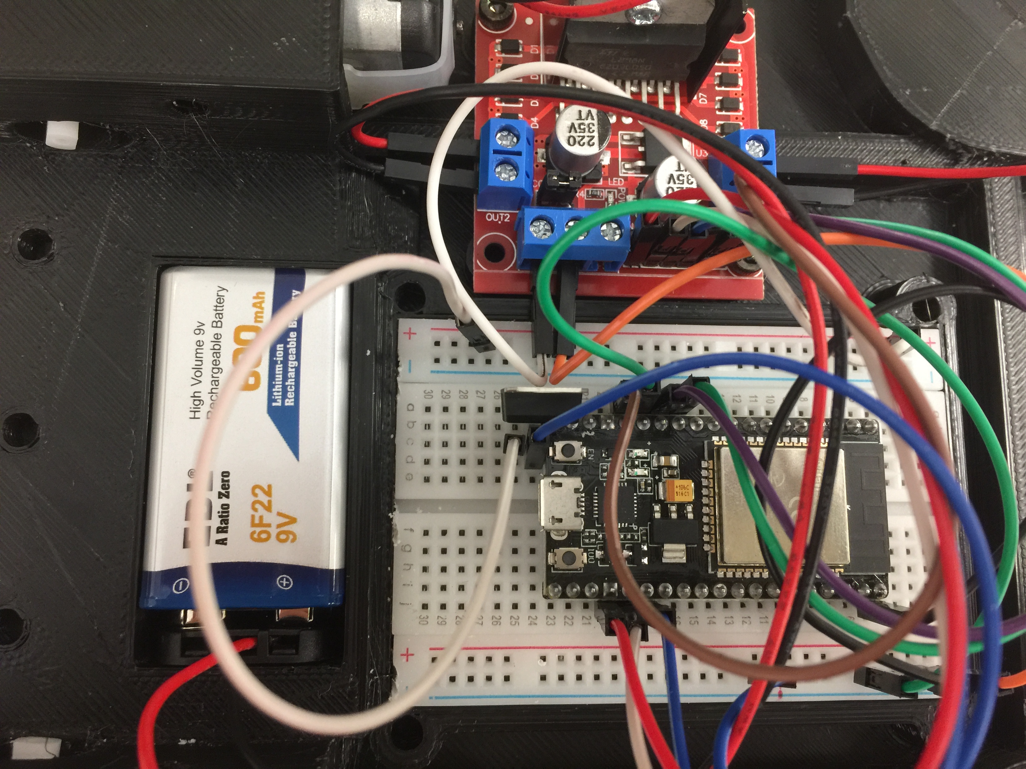
1. First Prototype
The main objective of the first prototype is to test the dimensions and driving. At this moment, the front armor plate was designed to be placed near the driving wheel, so there is a 45-degree ramp on the front.
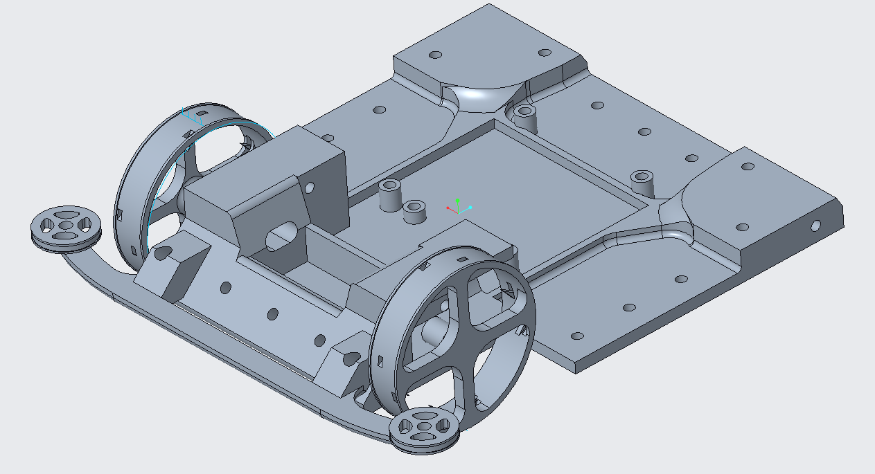
2. Second Prototype
In this version, the locations of the components were adjusted. New wheels were designed and built.
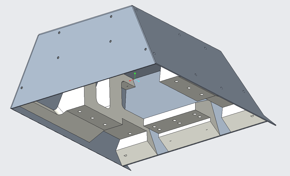
3. Final Design
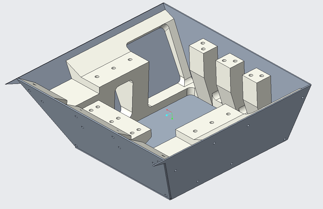
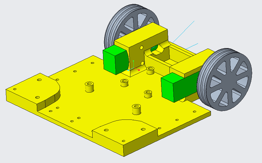
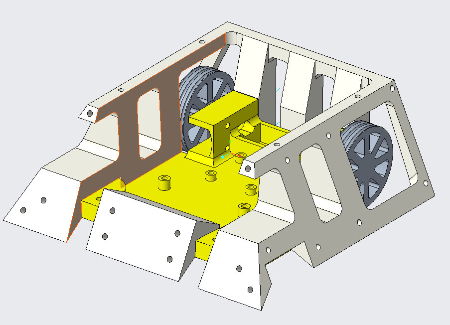
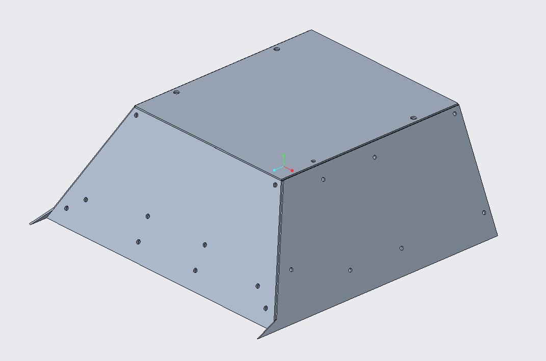
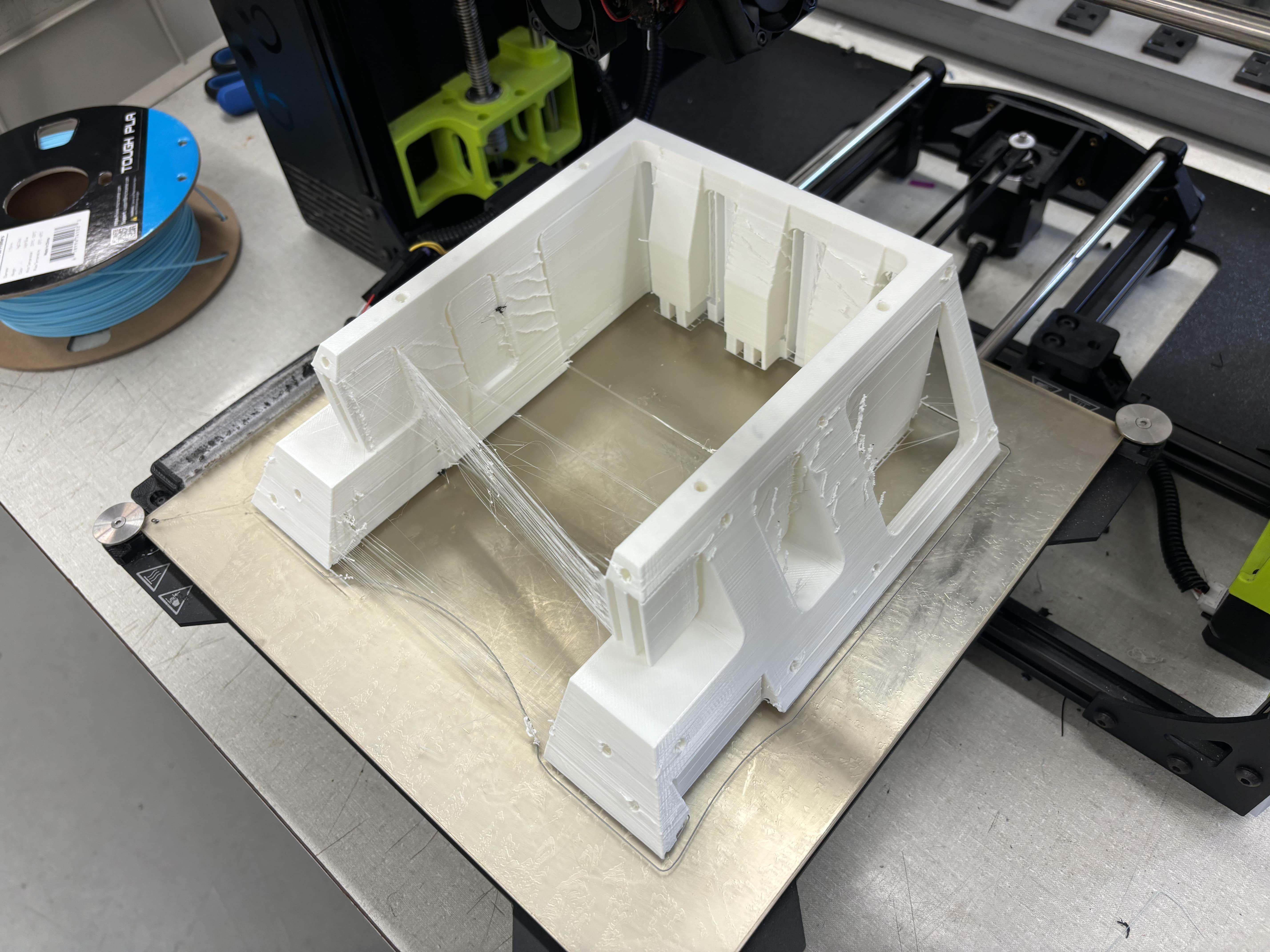
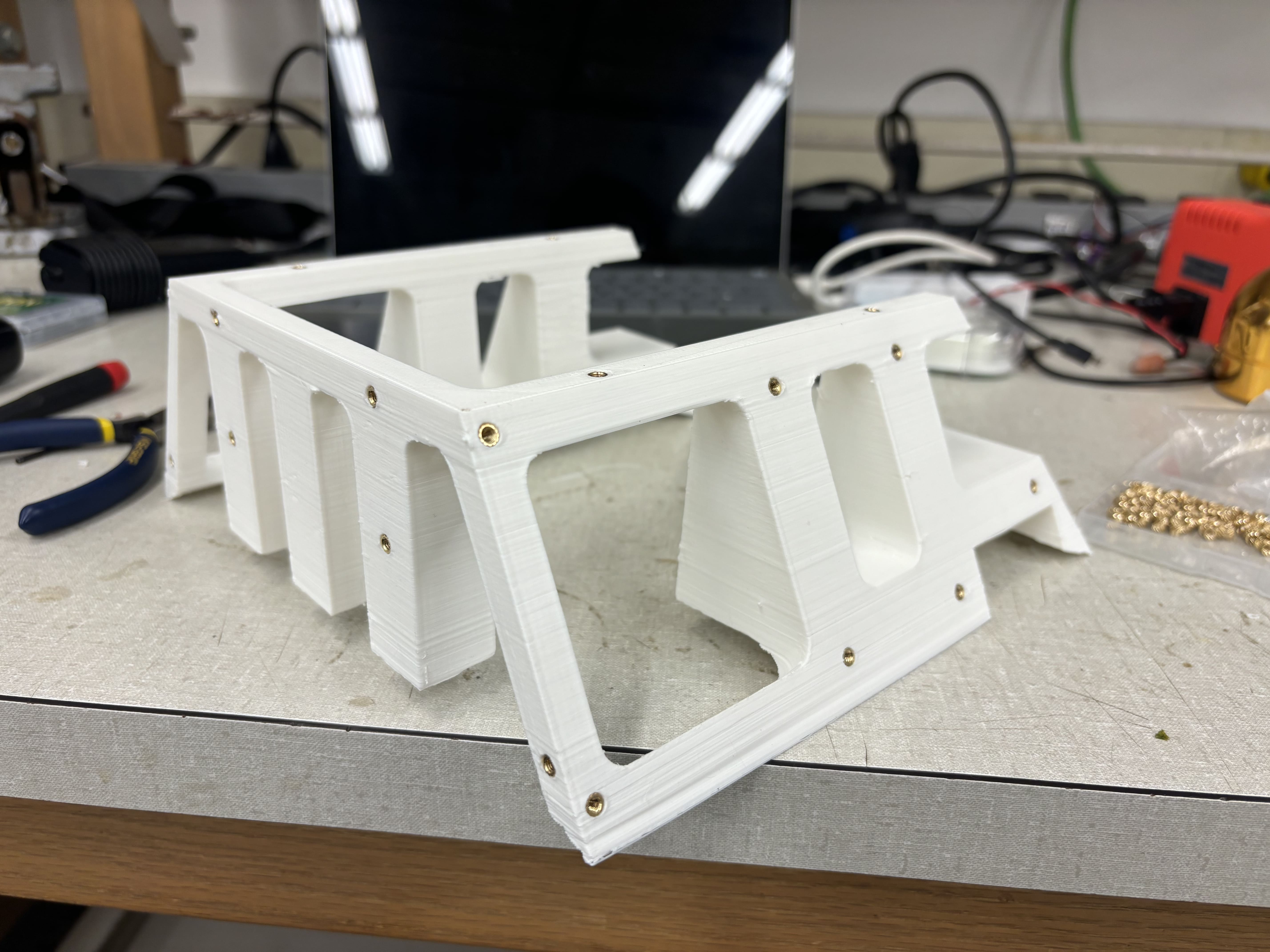
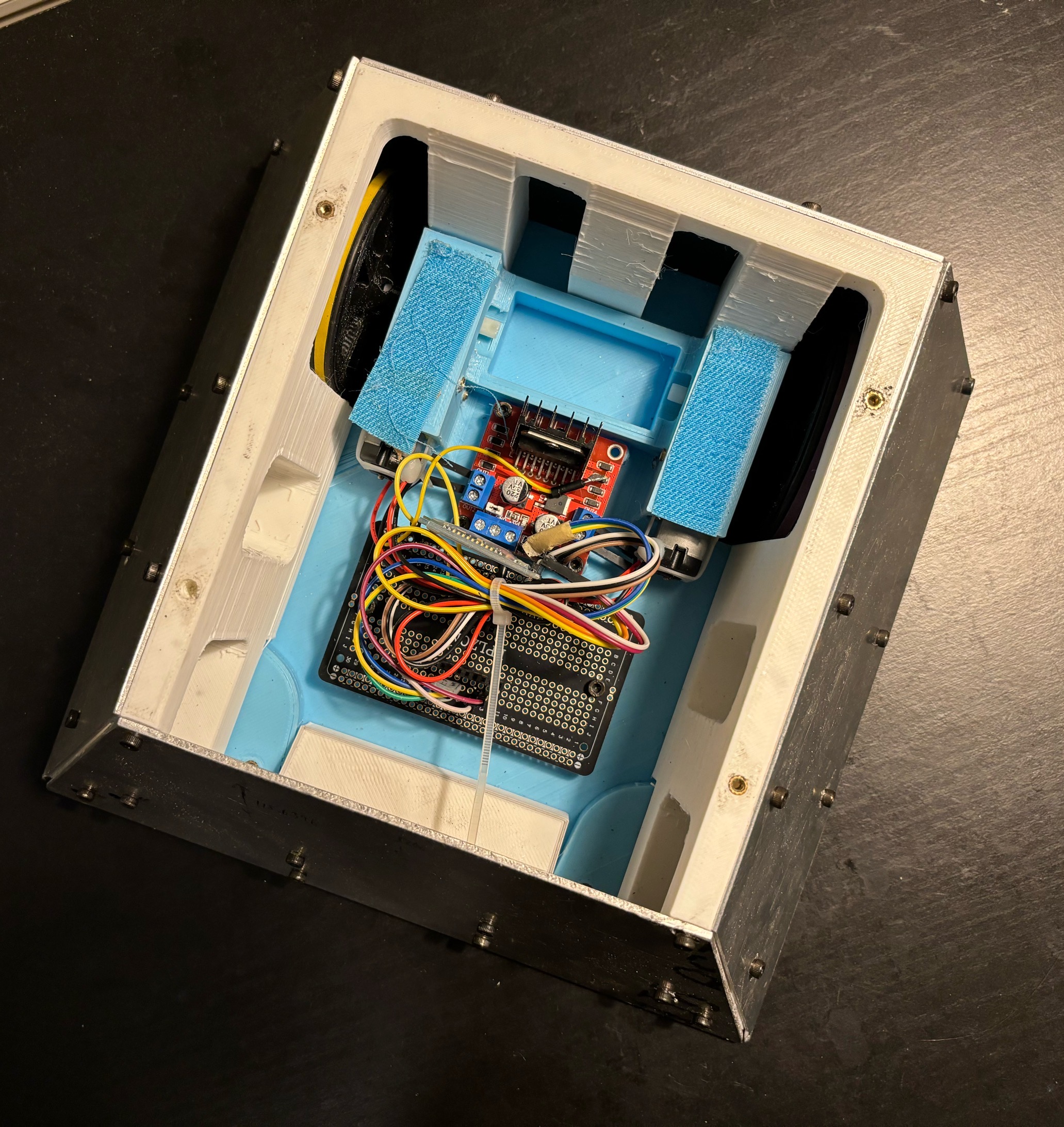
In the final version, the head and tail are switched so that the sloped front armor can be installed within the size limit. The order of design is this:
- The base of the chassis
- Wheels were assembled to the base.
- Armor plates were designed with 0.04” thickness
- armor skeleton was designed based on the base of the chassis and armor.
- location of the electrical components was decided.
IV. Racing and Battle Result
Best Time: 22 seconds (with bridge: 12 sec)
Best Official Time: 25 seconds (with bridge: 15 sec) (The racing specialist team had 22 sec)
Battle Rank: 2nd.
V. Reflections and Suggestions for Future-Semester-Students
- Think and ask for details of the rules
- Focus on racing, because this is individual, and you have the most situation control. In battle, you never know what will happen.
- Use omni wheel, and have three degrees of freedom for the movement, just like a drone can go forward, back, left, and right without changing the yaw, and add the yaw as the last control input. Basically, you want a control mode like a drone in a fixed horizontal plane (no change in altitude), so you need yaw control, pitch control (forward and back), and roll control (left and right).
- Use joysticks and PWM to control. Don’t use buttons. They are bad.
- Don’t use separate controls on the left and right wheels. Human can not synchronize them. A lot of groups did this, and their bots just couldn’t go straight.
- The group that specialized in racing had a gearbox, but it reduced the torque and hardly passed the bridge. We used directly yellow motor-geared drive with a wheel diameter of 67mm, it’s also fast and can pass the bridge with no pressure at all. Their turning radius was also large because they used a servo to turn and their large wheelbase.
- Use wide and soft rubber bands to make the wheels. Make grooves on the wheel hub for the rubber band. The given yellow wheel is super slippery. Use lead or iron blocks if necessary. True, the car without lead is lighter, but it won’t give you sufficient control. It’s super easy to get overshooted or poor response. It’s better to put it into 1st order system.
- Preserve enough time for testing.
- If possible, use a gyroscope and/or magnetometer and PID control to help you maintain the straight line.
- Use suspensions to define four points (wheels) on the same plane. Can use servos to make height-adjustable suspension if you want to do battle.
- Don’t get stuck on the flipper. Even it can’t flip your bot, your bot could get stuck and the wheels are off the ground. That’s why suspension and 4-wheel drive is important.
- I would add a one-time-use or a single-release mechanism as the weapon. Use super strong springs or rubber bands or whatever can store a large amount of energy and load it before you put it in the field. But make sure after release the weapon won’t mess you up, such as an extended part that could get you stuck somewhere.
- Simpler mechanisms can reduce the risk of breakdown.
- Conclusion: if I were doing it again, I would use 4 motors with 4 omni wheels with suspensions, and a center servo to control the height of the maximum height of the chassis base.
VI. Unused Weapon – Flipper
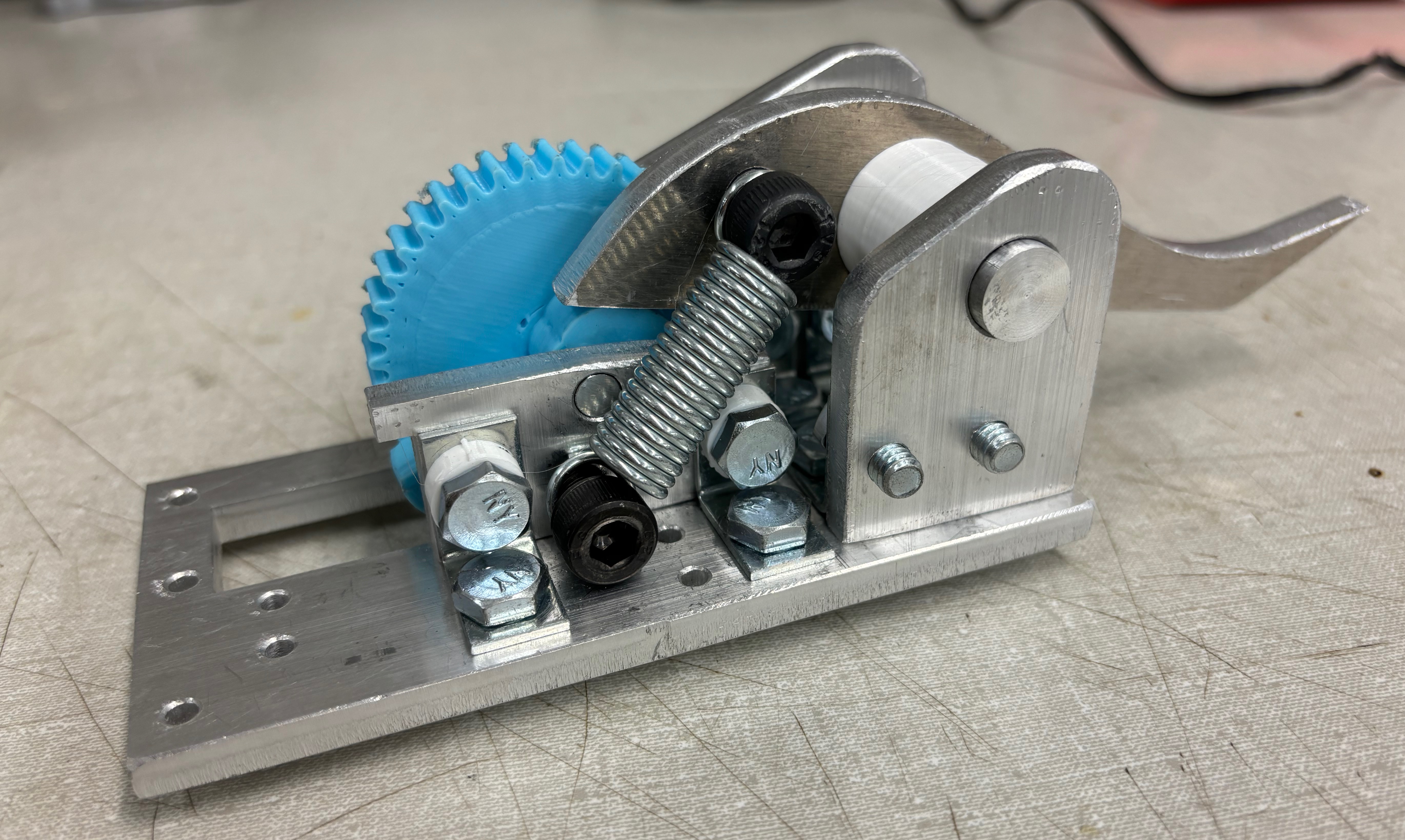
I spent entire week trying to make it work and figured out that the available spring, motors, servos, and power source I could get can’t make it work. I need more time to get better materials, including lubrication, stronger servo, a proper spring that has the right size and spring constant, and a better design, including changing the location of almost everything. After all, we had zero progress on the bot during this entire week, I also lost hours and hours of sleep.
So my suggestion is that if you want to use a flipper, use a strong 360 servo to control a lever instead of releasing some energy at an instant. To release the energy, it still needs a large force to overcome the friction. Not worth it.
