I. Intro
Date: Aug. – Nov. 2022
The pressure was built before I took this course. I was told the straw bridge competition was crude, and there must be someone fail the course. This course is basically the combination of ME270 Basic Mechanics I and ME323 Mechanics Of Material, so everything was very easy for me.
Engineers… they just know about calculation, they are not good at practical things.
One of the members from my group, September, 2022
Since it’s fall 2022, I just finished ME323 Mechanics Of Material which is about the stress, strain, and almost everything in a material during summer. The AT students didn’t know these things, so I became the one leading everyone in the group.
II. Objectives and Requirements
A. Goal
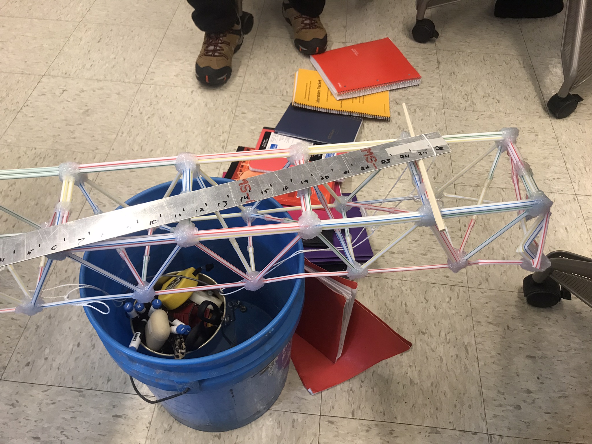
We are going to build a bridge that is at least 4” wide, crosses a 34” gap, and put mass on to test it.
The competition is scored based on these four aspects:
- Time to build: the first team to test get the highest score, which really sucks. Fastest doesn’t mean the best. We are here to design the bridge, not just rush the time just because the client wants to.
- Number of straws: least number of straws earns more points.
- Efficiency: more mass/straw earns more points.
B. Requirements
- destinated straws, hot glue, and tapes only.
- Tape or glue only 0.5 inch contact point.
- Straws may not be soaked or coated with glue or epoxy.
- Max deflection must be less than 1 inch.
More details can be found in the file.
III. Thought Experiment, Design, and Calculation
A. Useful Notes
- Top members need more second moment area to prevent bending or buckling.
- Tension on the bottom members, the joint must secure.
- Need member to support cross section, preventing forming parallelogram
- For #3, if making it concave down, like an arch bridge (just a little bit, so no one notice we are using an arch bridge, and we don’t have to sketch and calculate the members bc that’s tedious, we can if we have to), it could support more weight(?)
- Members does not only buckle in z axis, also in y axis, so increase I on both direction.
- Lab project pdf is assuming frictionless pins, actually it’s fixed-fixed ends. Leff = 0.5L.
- Gap is 34’’, min length 36’’, number of straw = total length of the straw(in) / 7’’. Test bar is rigid, spacing at 24’’
- When gluing it, as straight as possible, use tools to keep them straight. I can model it and 3d print it.
- Use hair-dryer to melt the hot glue but not the straws. Or melt them all and fuse the straws together.
- Triangle buckling at 8kg, hot glue break at least 5kg in tension with a diameter of 6mm, P=1.735MPa
- Make some spacing between the straws in each member?
B. Design
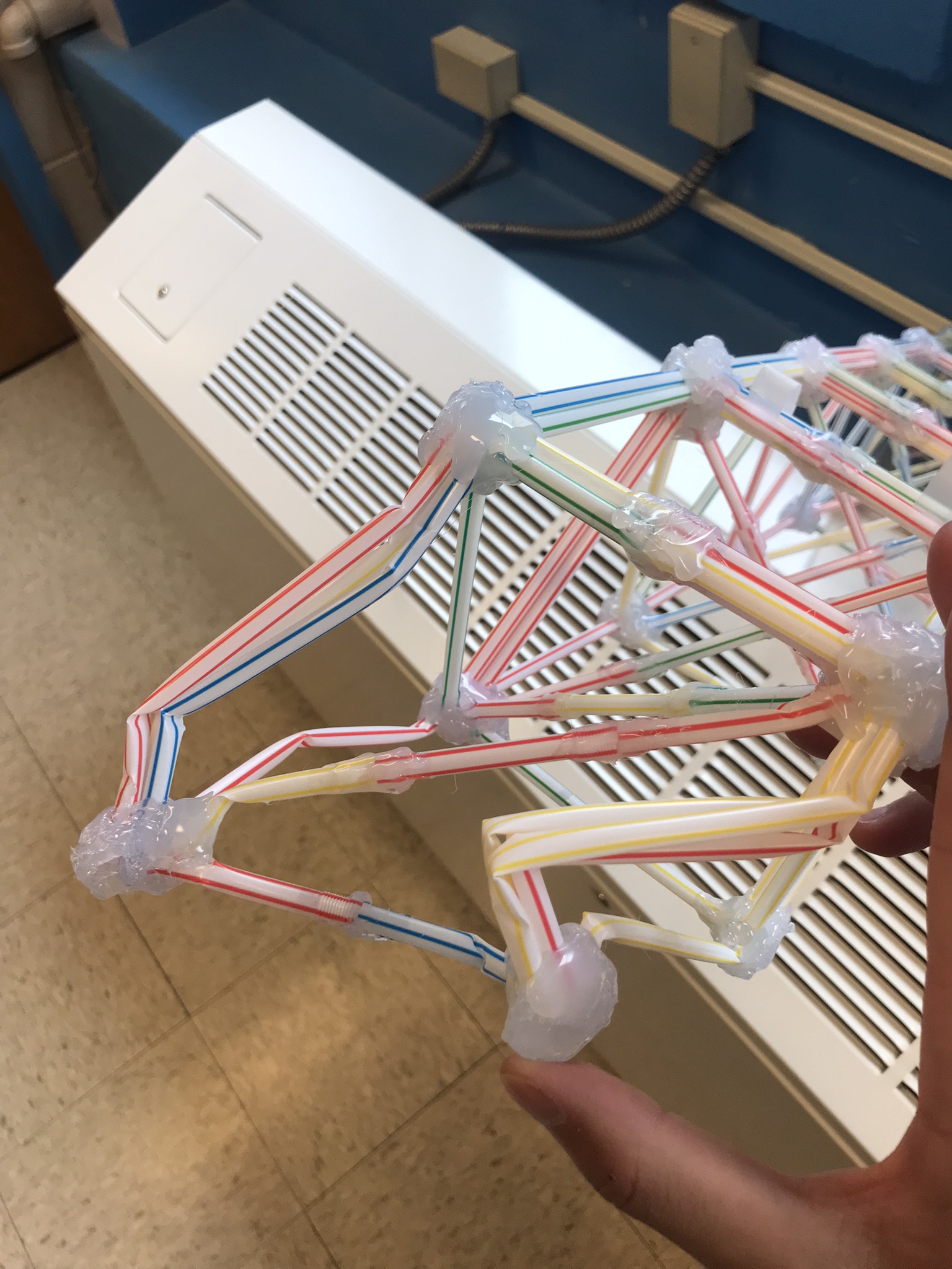
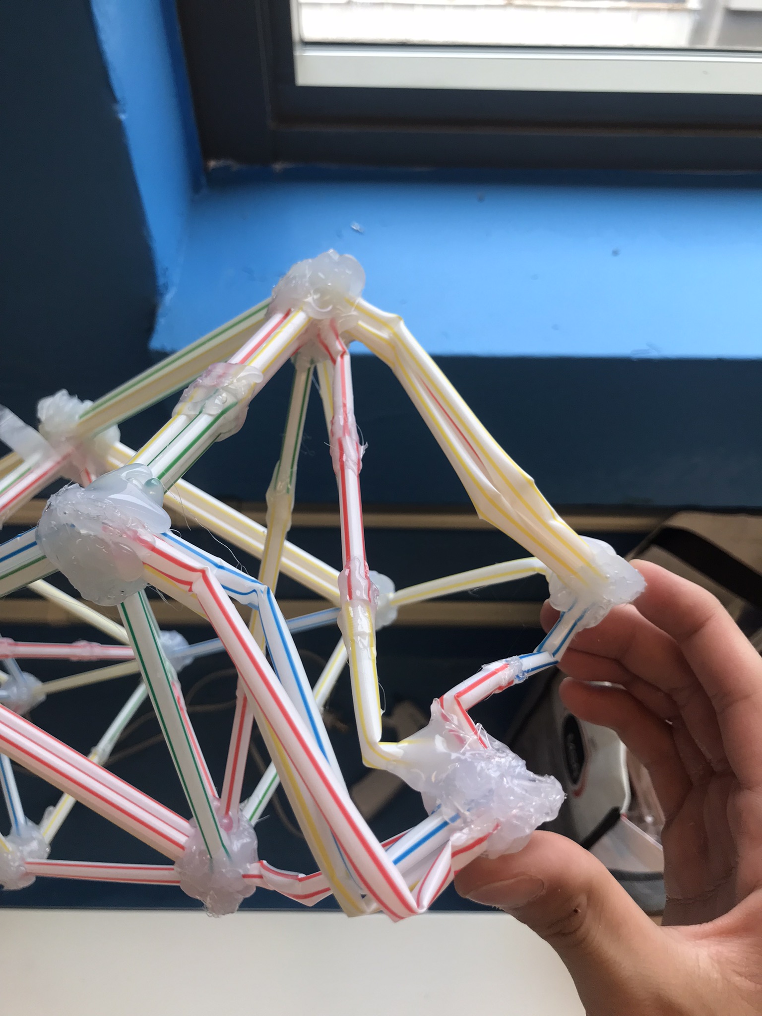
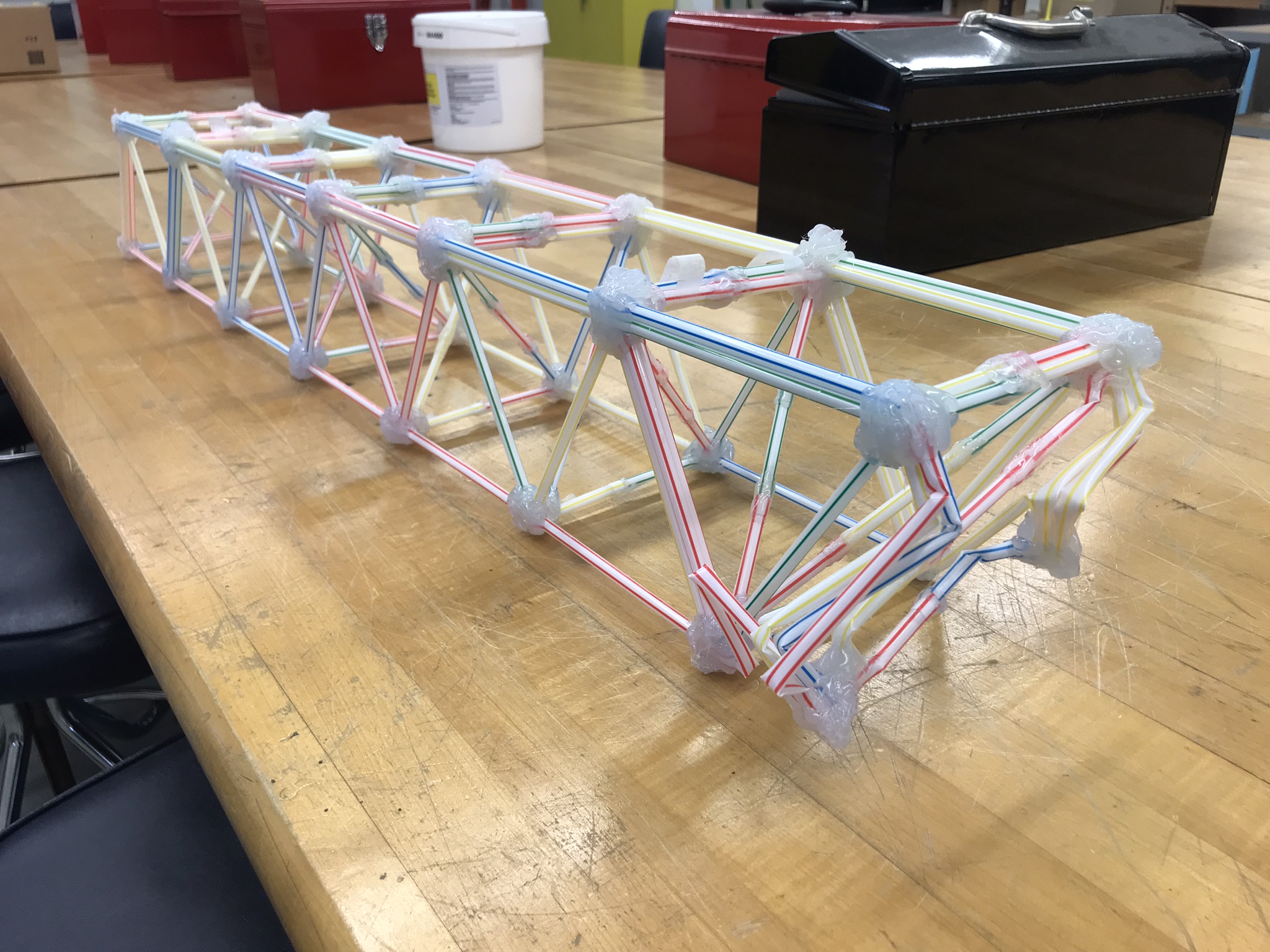
It doesn’t matter what I wrote above, we decided to use the classic triangle structure without any vertical members because they support zero load and increase the number of straws. It’s true that it can help prevent buckling, but the direction of buckling is uncertain. What if the horizontal member is trying to buckle in the direction of the vertical member? Then the vertical member also has the potential to buckle. I decided to use a triangle cross-section for the top horizontal member to gain the advantage of the fourth power in the second moment area.
Only 5 inches of the 7” straw can be used because of the bending section on the straw. The rest of the 2” were used to form the triangle at the cross sections of the bridge.
C. Calculation
All members which were in compression were in the triangle cross-section
IV. Bridge I
A. Construction
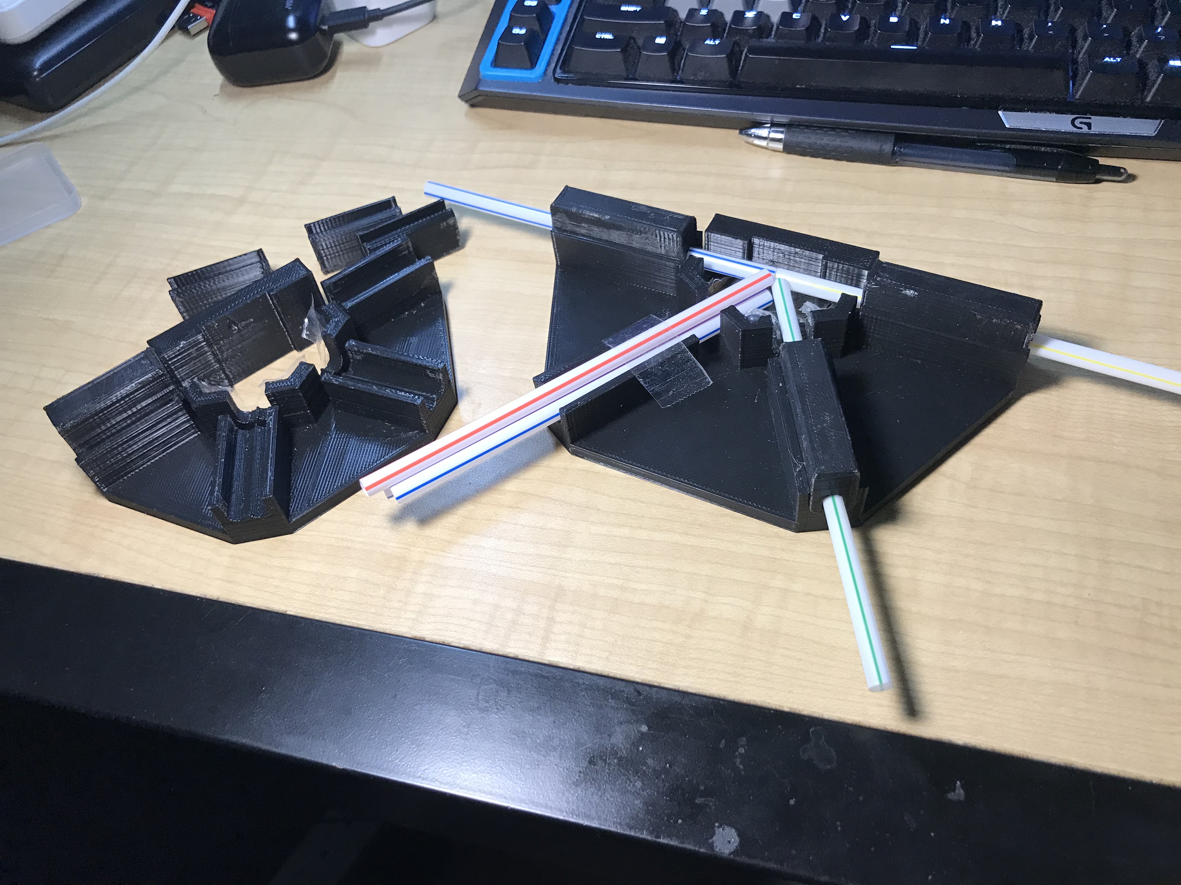
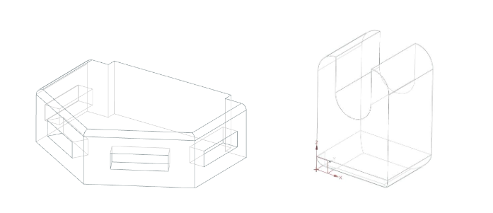
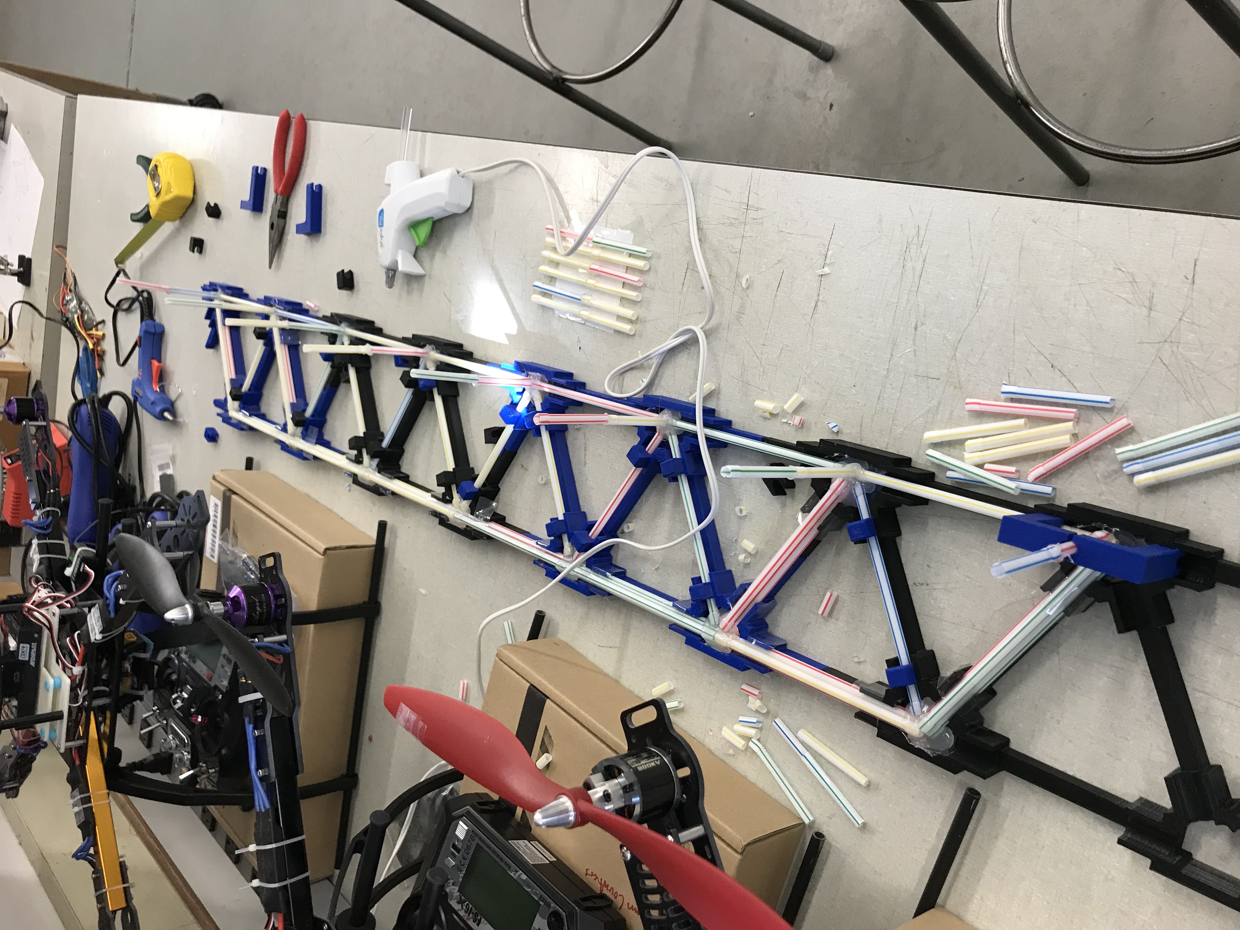
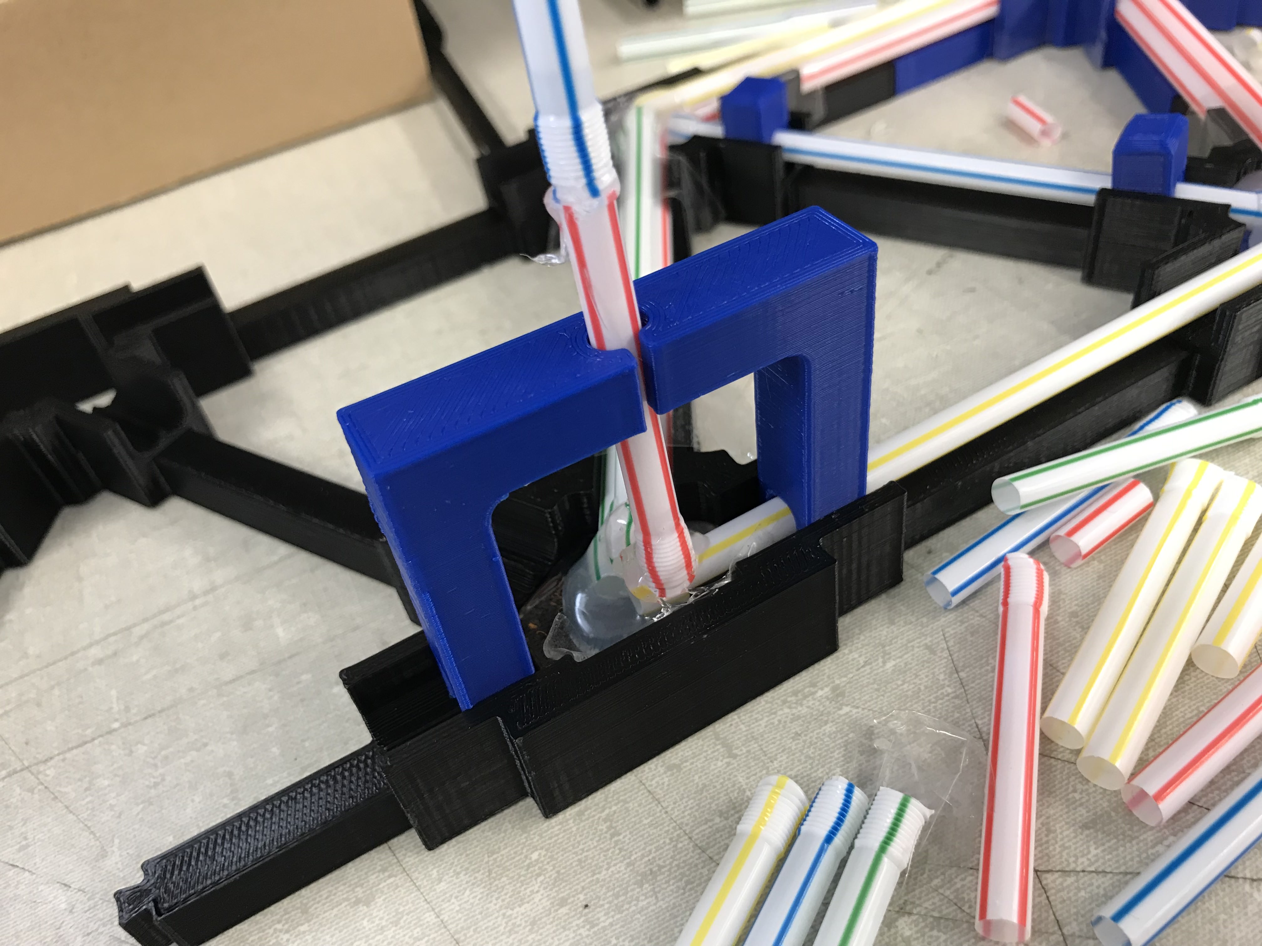
To keep the precision of the construction, I designed and printed a mold. In this way, all the angles were precisely 60 degree. There were also extra pieces that held the straws in place and horizontally. Once all the straws were in there, a large amount of hot glue was injected into the case. Finally, the joint was pushed out, and a section is done.
B. Test
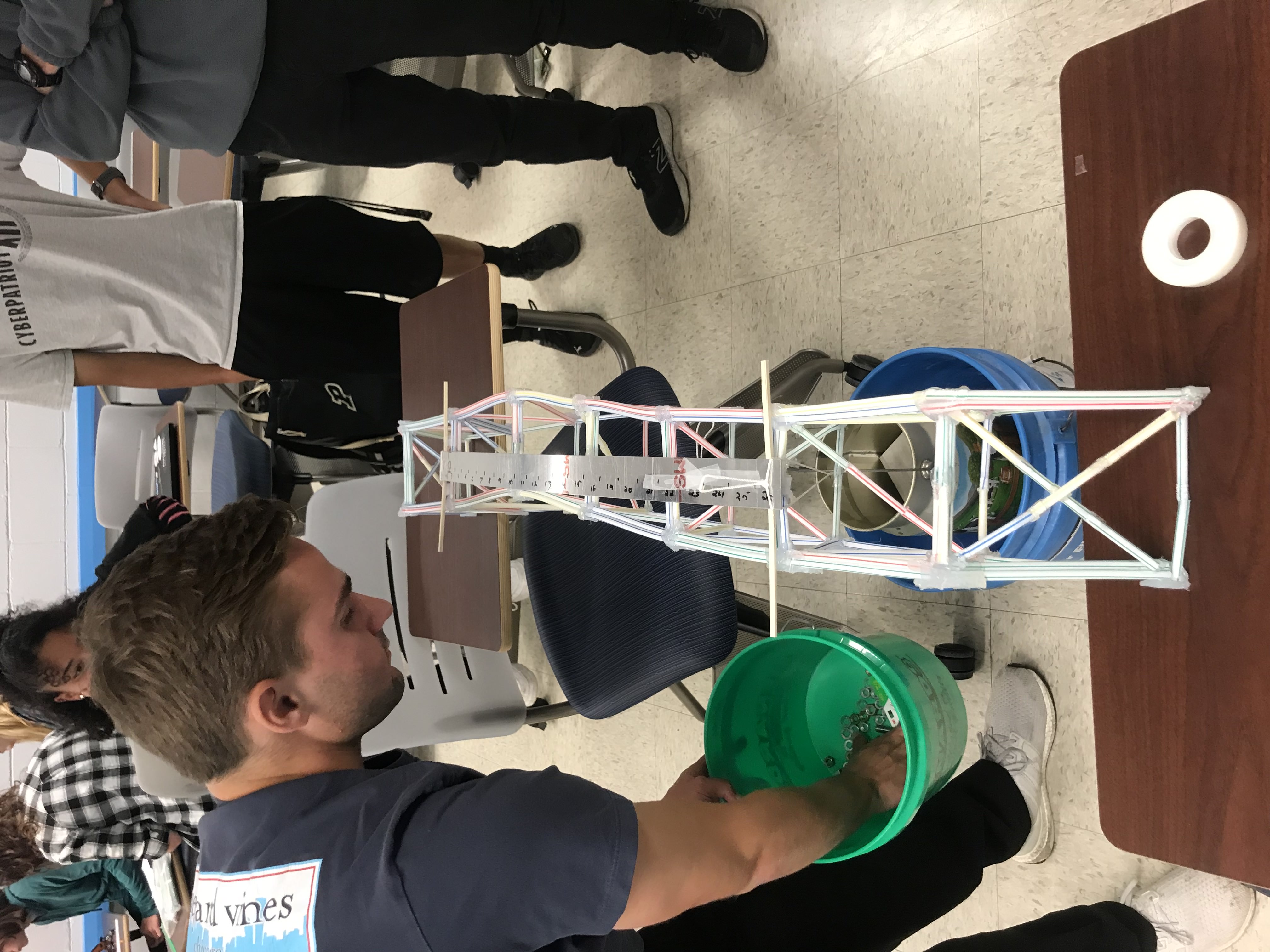
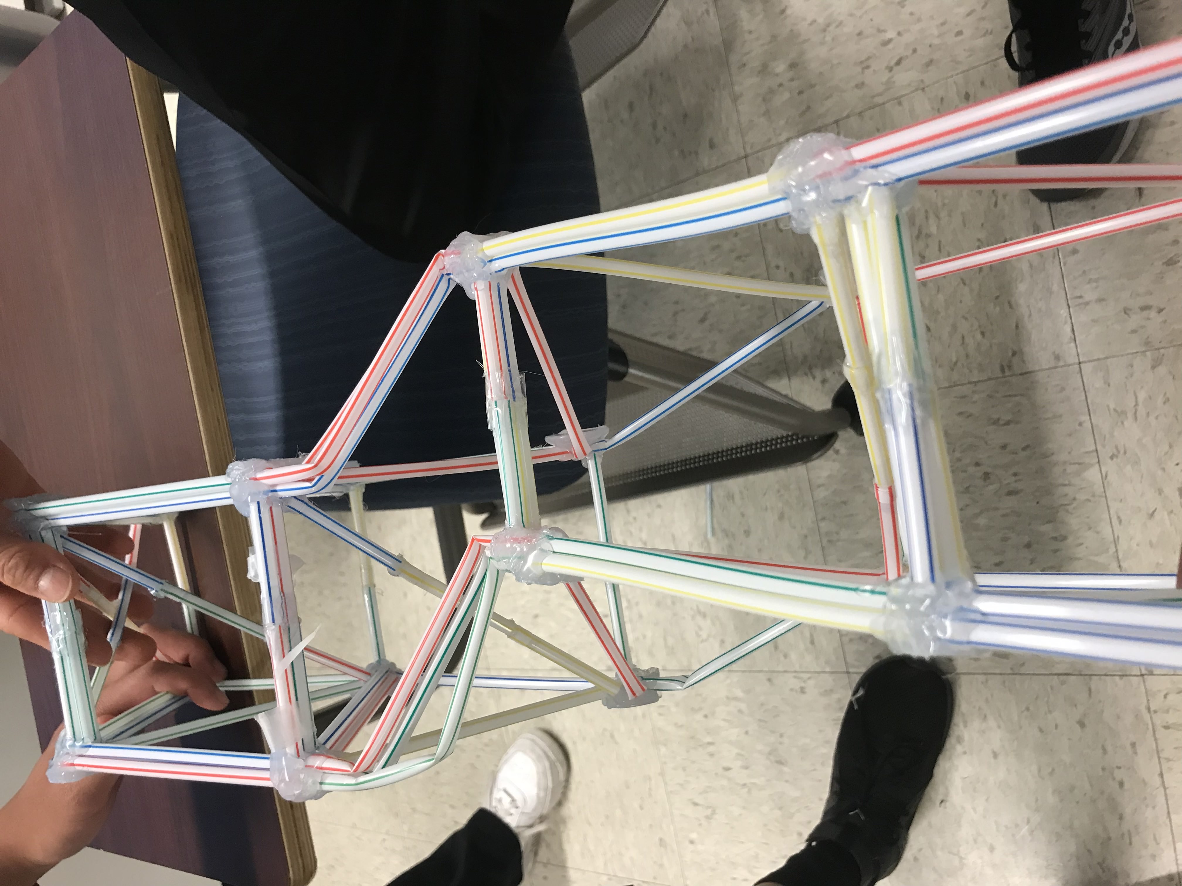
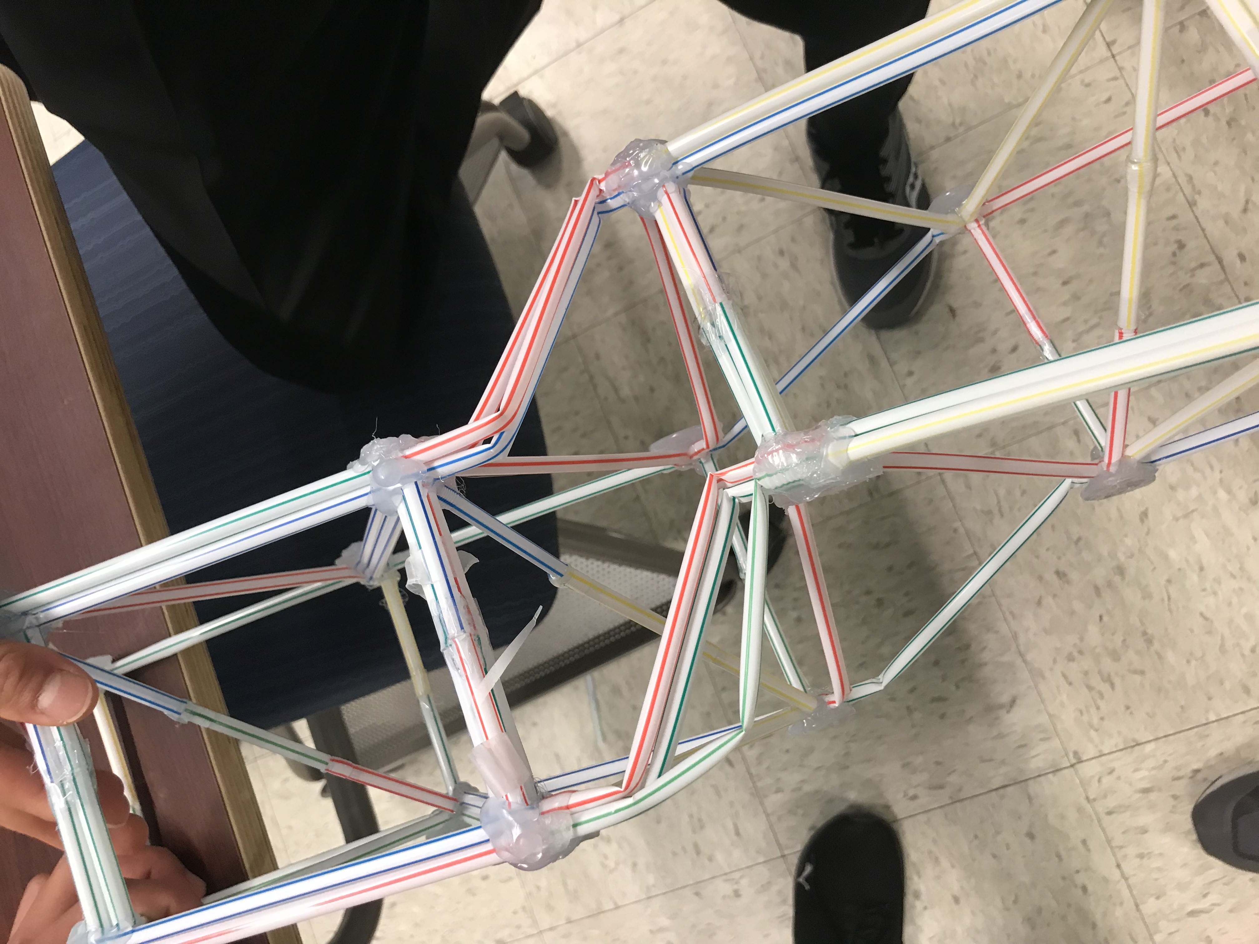
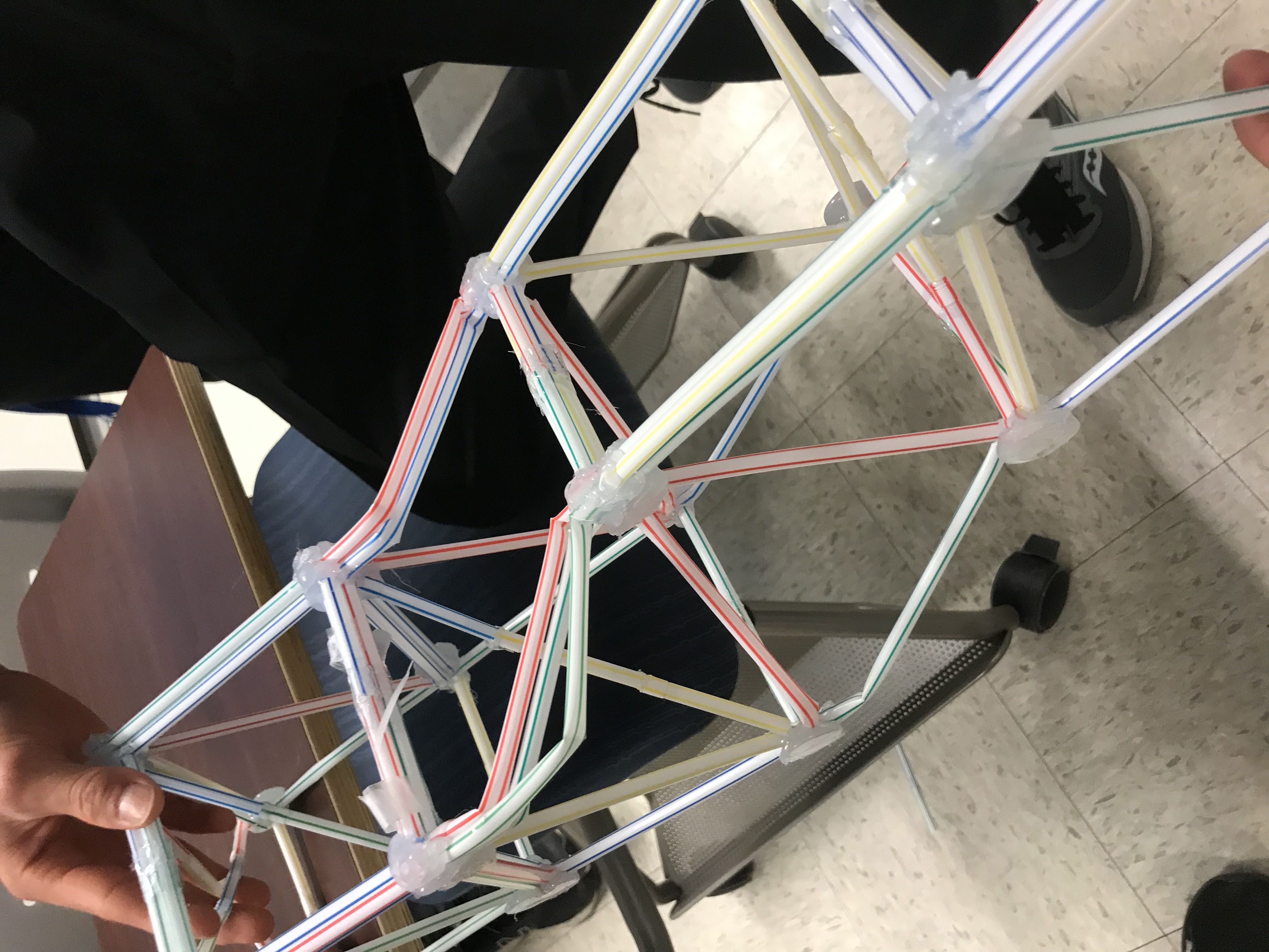
The test didn’t go well. Partially filled members for the cross-section of the bridge didn’t work. It failed where there wasn’t a member.
V. Construction II
A. Construction
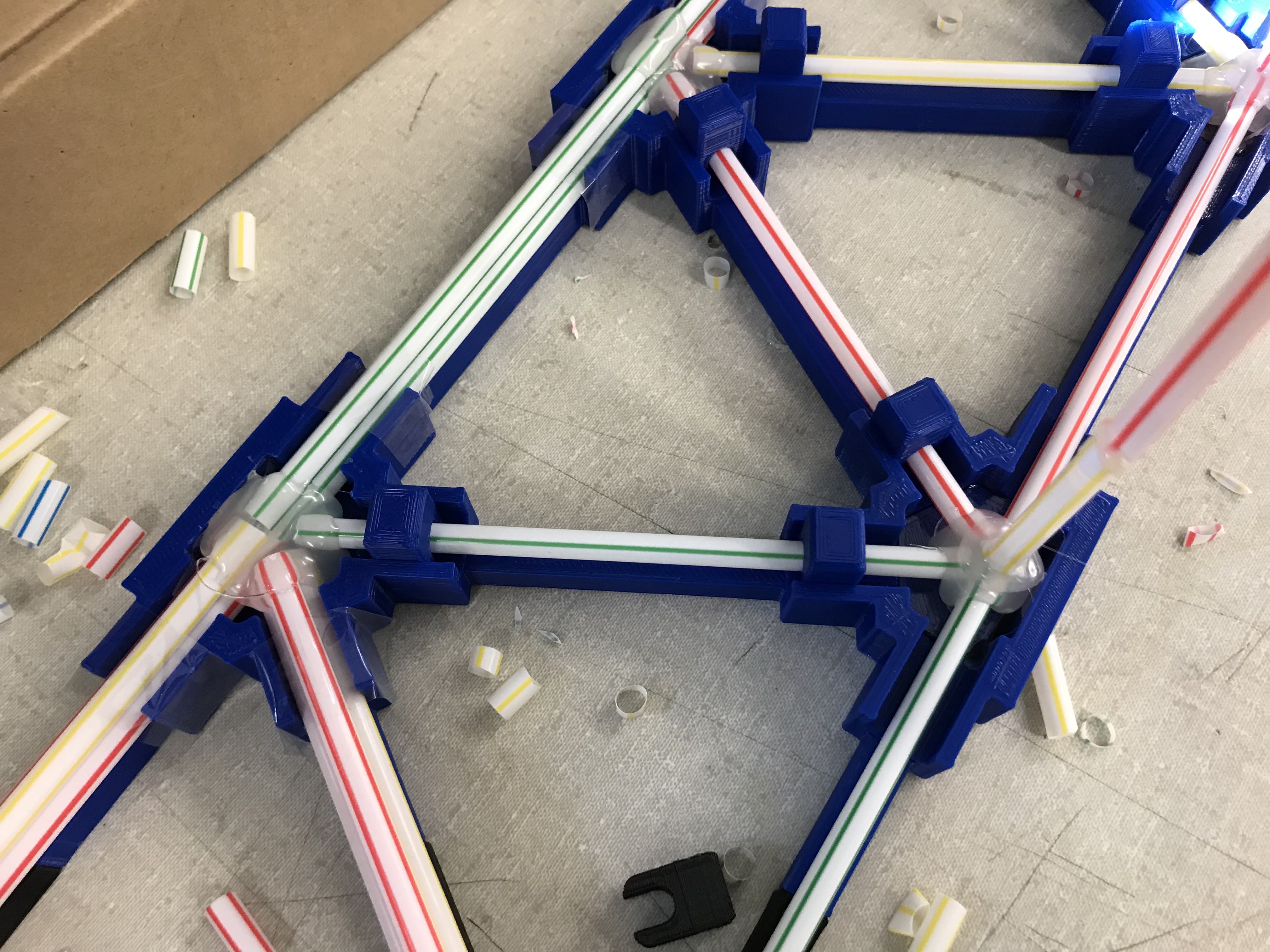
This time I was adding the supporting members to all cross-section area of the bridge. Meanwhile, I designed a better version of the mold that will fuse all the members of one side together at once.
B. Test
It supported 10.084 kg.
